


The short answer
You cannot choose an arc-flash suit from switchgear voltage alone. There is no technically defensible rule such as “400 V requires Category 2,” “11 kV requires APC 2,” or “medium voltage always needs a 40 cal suit.” The correct selection depends on:
- the exact task—normal switching, racking, opening a compartment, testing, fuse work or maintenance;
- the condition and construction of the switchgear—doors secured, correctly installed and maintained, evidence of impending failure, internal-arc classification, remote operation and exhaust path;
- the prospective fault current and arcing current at that bus;
- the total clearing time of the protective device at the arcing current, including the slower reduced-current case;
- the working distance, enclosure size and electrode configuration; and
- the assessment system being used: IEC open-arc values, IEC box-test classes, or the NFPA 70E/IEEE 1584 incident-energy or table method.
The result selects a complete, compatible PPE system: body clothing, head and face protection, safety glasses, hearing protection, gloves and footwear. Arc-flash clothing addresses the thermal hazard. It does not by itself provide shock insulation, hearing protection, protection from pressure waves, projectiles, toxic smoke or hot oil.
Safety-critical limitation: De-energization is the primary control. PPE is the last line of defence and does not make unjustified energized work acceptable. An electrically safe work condition must be established and verified whenever the task permits it. Final PPE selection, energised-work justification and boundaries must be approved by the responsible employer and a competent/qualified person under the applicable law and site procedure.
1. Understand the hazards before choosing clothing
1.1 Arc flash, arc blast and electric shock are different hazards
An internal fault can create several hazards at the same time:
- Arc-flash thermal energy: radiant and convective heat that can ignite clothing and cause skin burns. This is what an arc rating or APC class primarily addresses.
- Arc blast: pressure, sound, molten metal, fragments and doors or panels that may move. A higher-calorie suit is not a pressure-rated enclosure.
- Electric shock: current through the body after contact or approach to exposed live parts. Shock risk is controlled by safe approach, barriers, insulating tools and voltage-rated rubber gloves or other insulating PPE—not by the cal/cm² rating of the suit.
- Secondary hazards: toxic decomposition products, hot insulating oil, fire, falls, restricted escape and heat stress.
IEC 61482-2 expressly covers protective clothing against the thermal hazards of an electric arc and does not claim protection from electric shock, noise, pressure, hot oil, head/face hazards or every other consequence. Head, face and eye protection is addressed separately by standards including IEC 62819, while insulating gloves are covered by IEC 60903.
1.2 AR is not the same as ordinary FR—and cotton is not an arc rating
Arc-rated (AR) clothing has been tested for electric-arc thermal performance and carries an arc rating or box-test class. Flame-resistant (FR) describes flame behaviour, but an FR claim alone does not establish an arc rating. Untested cotton, even heavy cotton, is not “8 cal” clothing. Ordinary polyester, nylon, polypropylene, acetate and spandex can melt into the skin and are especially dangerous unless they are part of an approved, tested fabric system.
Every AR garment is intended to resist flame propagation, but not every garment marketed as FR is tested for electric-arc exposure. Read the sewn-in label and the manufacturer’s current technical data and declaration of conformity.
2. Does a switchgear operator need arc-flash PPE for every operation?
Not necessarily—but “doors closed” is not a universal exemption. First decide whether an arc-flash event is reasonably likely for the task and condition. Then, if it is likely or if the local procedure requires protection, select the PPE level.
The following matrix is a screening guide, not a permit to work:
| Task and condition | Typical likelihood decision | What must be checked before the decision |
|---|---|---|
| Reading a meter, relay display or indicator through a closed window; no operation | Often low when equipment is in normal operating condition | Correct installation and maintenance; all covers secured; no smell, noise, heat, contamination, tracking, damage or alarms |
| Operating a breaker, switch, contactor or starter with doors closed | May be considered unlikely under the NFPA “normal operating condition” criteria | All normal-condition criteria; operating mechanism and door interlocks; current risk assessment; whether local rules still require baseline AR clothing |
| First operation after installation, intrusive maintenance or a protection change | Treat as elevated until the installation is verified | Commissioning results, settings, phasing, mechanical condition, protection and remote-operation options |
| Operating equipment with signs of impending failure | Arc-flash event is more likely | Stop, isolate remotely where possible, establish an electrically safe condition and investigate |
| Racking a circuit breaker or starter, even with the outer door closed | Commonly treated as a likely arc-flash task | Arc-resistant design and tested racking configuration, shutters, maintenance state, remote racking and label/study |
| Opening a door or removing a cover that exposes energized conductors or circuit parts | Likely | Energized-work justification, approach boundaries, shock PPE, incident energy/APC assessment |
| Voltage testing, troubleshooting or diagnostics on exposed energized parts | Likely | Exact probe position, hand/face distance, test instrument category, shock protection and study result |
| Inserting/removing fuses or working on bolted pressure switches | Likely unless an applicable assessment says otherwise | Fuse type, current-limiting region, condition, mechanism, clearing time, doors and remote method |
NFPA guidance treats operation of a circuit breaker or switch as having a low likelihood only when the equipment is properly installed, properly maintained, used according to instructions, has doors/covers closed and secured, and shows no evidence of impending failure. Racking, energized testing, opening covers and many abnormal conditions remain higher-risk tasks. See NFPA’s explanation of normal operation and equipment condition.
A useful German screening rule—but only within its scope
DGUV Information 203-077 provides a simplified German selection method for work on or near electrical installations. It identifies limited situations in which special arc-protective PPE may not be technically required, including certain control/measurement circuits protected at no more than 25 A, some circuits up to 400 V protected at no more than 63 A when long work clothing is worn, and AC systems up to 400 V with prospective short-circuit current below 1 kA. These are not global exemptions: shock, fuse ejection, process hazards, local law and employer rules still apply, and the conditions must be verified.
3. The standards map: which document does what?
| Region / purpose | Main document | Practical role |
|---|---|---|
| International / product | IEC 61482-2:2018 | Performance requirements for arc-protective clothing; permits open-arc and/or box-test information according to the product and marking route |
| International / open-arc test | IEC 61482-1-1:2019 | Determines ELIM, ATPV and/or EBT under an open-arc test; produces an energy value, not an APC class |
| International / box test | IEC 61482-1-2:2014 | Classifies material/garment performance as APC 1 or APC 2 in a constrained box-test exposure |
| Germany / selection | DGUV Information 203-077 | Practical box-test-based risk assessment and selection for work on or near electrical installations |
| Germany / operation | DIN VDE 0105-100 and DGUV Vorschrift 3 | Organisational and operational requirements for electrical installations and work |
| United States / safe work | NFPA 70E, 2027 edition | Requires risk assessment and offers either an incident-energy method or a PPE-category table method |
| Engineering calculation | IEEE 1584-2018 | Calculates arcing current, incident energy and arc-flash boundary for covered three-phase AC systems from 208 V to 15 kV |
| US product testing | ASTM F1506, F1959, F2178, F2675 and related standards | Clothing, material arc rating, face protection and hand-protection tests; see ASTM’s current safety standards overview |
| Switchgear containment | IEC 62271-200 and IEEE C37.20.7-2024 | Internal-arc/arc-resistant switchgear classification and testing—not a clothing-selection standard |
Edition warning: a workplace may legally reference a national adoption or a contractually specified edition. Record the exact edition used in the assessment. This article uses the current editions available on the review date above; it does not replace a purchased copy of the standard.
4. Rating terms that must not be mixed
4.1 ATPV, EBT and ELIM: open-arc energy values
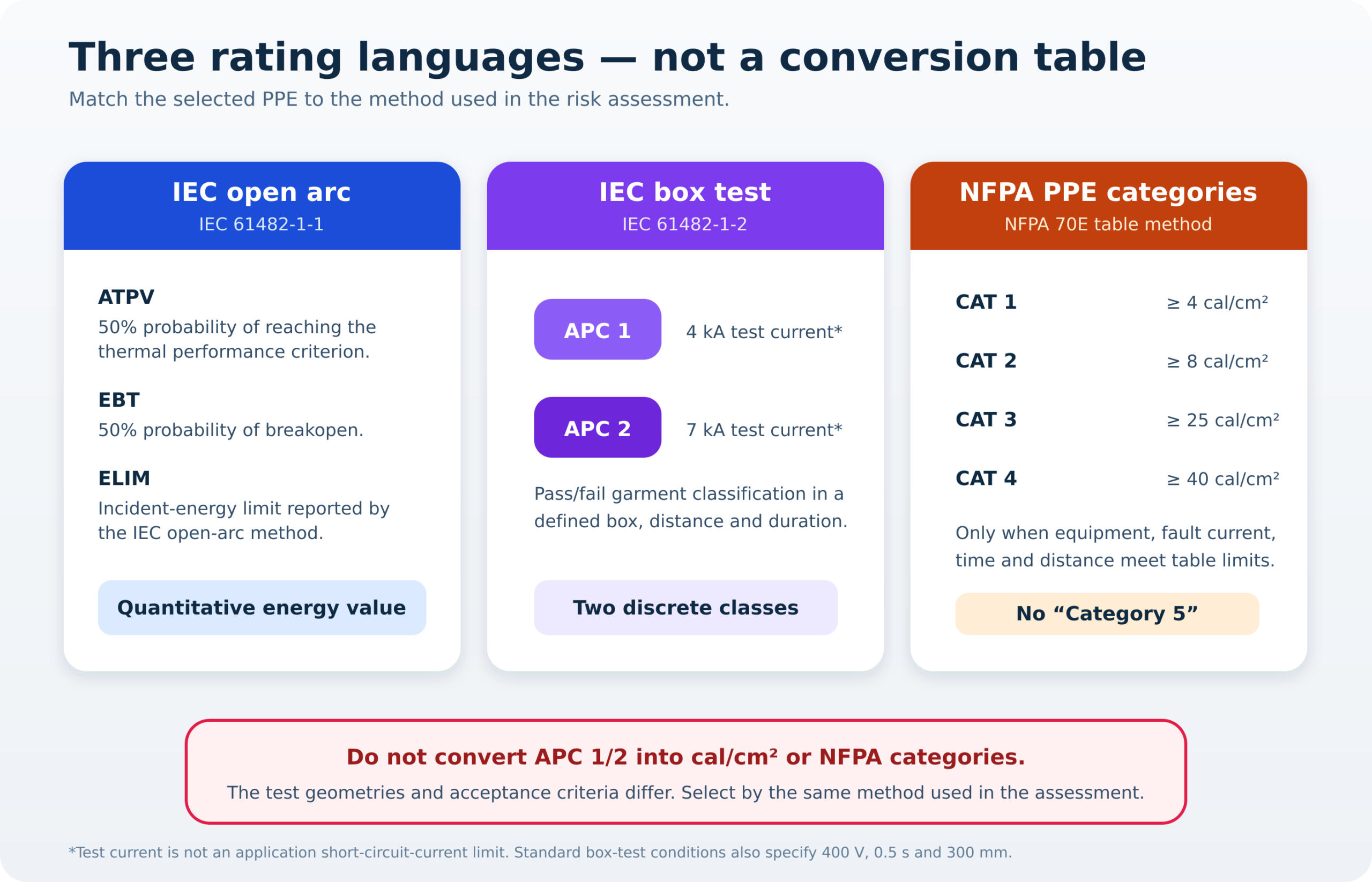
- ATPV (Arc Thermal Performance Value): incident energy associated with a 50% probability that heat transfer through the material reaches the applicable burn criterion.
- EBT (Energy Breakopen Threshold): incident energy associated with a 50% probability of material breakopen. When EBT governs, the fabric may open before the heat-transfer criterion governs.
- ELIM (Incident Energy Limit): an IEC open-arc result intended to report a no-predicted-effect limit from the test data using the IEC statistical criteria.
The label may report energy in cal/cm² or kJ/m². For unit conversion:
An open-arc-rated ensemble is selected so that its applicable arc rating is at least the calculated incident energy, with the employer’s required margin. Never add the ratings of separate layers unless that exact layered system has been tested and rated as a system.
4.2 APC 1 and APC 2: box-test classes
IEC 61482-1-2 uses a directed arc inside a specified plaster box at a fixed distance and duration. The standard classifications are:
| Box-test class | Standard test current | Standard voltage, duration and distance | Nature of result |
|---|---|---|---|
| APC 1 | 4 kA | 400 V, 0.5 s, 300 mm | Pass/fail against the test criteria |
| APC 2 | 7 kA | 400 V, 0.5 s, 300 mm | Pass/fail against the more severe exposure |
Two points prevent serious mistakes:
- The 4 kA and 7 kA values are laboratory test currents, not maximum switchgear fault currents. An APC 1 garment can be correctly selected at a bus with bolted fault current greater than 4 kA when the full DGUV assessment demonstrates sufficient protection; the reverse can also be true.
- APC 2 is not equivalent to 25, 40 or any other number of cal/cm². The geometry, measurement and acceptance criteria differ. There is no universal APC-to-calorie conversion.
DGUV uses mean reference arc energies of approximately 168 kJ for APC 1 and 320 kJ for APC 2 within its calculation framework. Those values belong to that specific selection method; they are not generic open-arc ratings printed on the garment.
4.3 NFPA 70E PPE categories
The NFPA table method has four categories. The number is a category label—not the calculated incident energy.
| NFPA 70E category | Minimum arc rating of the clothing system | Typical body/head configuration in the table method* |
|---|---|---|
| Category 1 | 4 cal/cm² | AR long-sleeved shirt and trousers or AR coverall; AR face shield or hood as specified |
| Category 2 | 8 cal/cm² | AR shirt/trousers or coverall; AR hood, or AR face shield plus AR balaclava as specified |
| Category 3 | 25 cal/cm² | AR suit system with arc-flash suit hood |
| Category 4 | 40 cal/cm² | AR suit system with arc-flash suit hood |
*The complete table also calls for hard-hat, eye, hearing, hand and footwear protection as applicable. Use the actual edition and table; this summary is not a substitute.
There is no NFPA Category 5. An incident energy above 40 cal/cm² is not automatically “Category 5,” nor does it automatically mean work is permissible in any available high-rating suit. It should trigger engineering review, energy reduction, remote operation or de-energization. If justified work remains, the PPE must be selected by an appropriate incident-energy assessment and approved work plan.
4.4 Do not use both NFPA methods on the same equipment
NFPA 70E permits:
- the incident-energy analysis method, which calculates energy at a stated working distance and selects an ensemble with an adequate arc rating; or
- the PPE-category table method, but only if the equipment type, fault-current range, maximum clearing time and minimum working distance all meet the table’s limits.
Do not calculate 7.2 cal/cm², round it to “Category 2,” and then treat the category table as the calculation. For the incident-energy method, the label should state the incident energy and working distance (or another permitted site-specific field), not both calculated incident energy and a PPE category. NFPA explains the separation in its guidance on correct use of the two methods.
5. A field-ready selection workflow
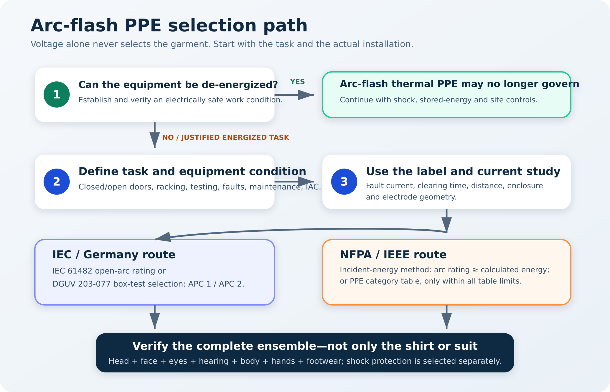
Step 1 — Establish an electrically safe work condition if possible
Apply the governing isolation procedure, identify every source, open disconnecting devices, secure against reconnection, verify absence of voltage with an adequately rated tester and address stored energy. The precise sequence comes from the applicable regulation and site procedure. “The process cannot stop” is not, by itself, a technical justification for energized work.
Step 2 — Write the exact task as a verb-object-location statement
“Operate switchgear” is too vague. Better task definitions are:
- operate feeder breaker Q2 from the local front control with all doors secured;
- rack breaker Q2 from connected to test position using a 6 m remote racking lead;
- open the LV cable compartment and test voltage at the outgoing terminals;
- replace three NH fuses in the incomer with the upstream source energized; or
- inspect the relay through the viewing window without operating equipment.
Working distance and exposure geometry change with the task. A label calculated at 455 mm for the torso cannot be blindly applied to a hand or face that will be 250 mm from an exposed source.
Step 3 — Confirm equipment condition
Check the inspection/maintenance status and look for:
- loose or missing fasteners, damaged doors, defeated interlocks or wrong replacement parts;
- moisture, dust, conductive contamination, vermin, corrosion or blocked ventilation;
- abnormal heat, smell, sound, vibration, partial-discharge indications, soot or tracking;
- protection alarms, high contact resistance, repeated trips or unexplained fuse operation;
- the correct breaker rating, settings and control power; and
- correct installation of pressure-relief flaps, exhaust ducts and room clearances for IAC/arc-resistant gear.
If the condition is abnormal, stop treating the task as “normal operation.”
Step 4 — Read the label, but verify that it is still valid
A useful arc-flash label identifies the equipment and includes, as applicable:
- nominal system voltage;
- arc-flash boundary;
- calculated incident energy and corresponding working distance or the permitted PPE category/site-specific PPE level;
- minimum required arc rating; and
- the study/label date and equipment identifier.
NFPA 70E requires labels to be reviewed for accuracy when the electrical system changes and the supporting incident-energy analysis to be reviewed at intervals not exceeding five years. A label becomes suspect after transformer, utility-source, conductor, generator, motor, breaker, fuse, relay-setting, operating-mode or enclosure changes.
Step 5 — Identify which assessment method produced the result
- IEC/DGUV box-test route: select APC 1 or APC 2 only after the DGUV comparison or another competent assessment based on IEC 61482-1-2.
- IEC open-arc route: select a tested ensemble whose applicable ELIM/ATPV/EBT or stated arc rating meets the assessed incident energy.
- NFPA/IEEE incident-energy route: use a validated IEEE 1584 implementation within its scope; select arc rating equal to or greater than incident energy.
- NFPA table route: verify every row limitation before using Category 1, 2, 3 or 4.
Step 6 — Select every component as one ensemble
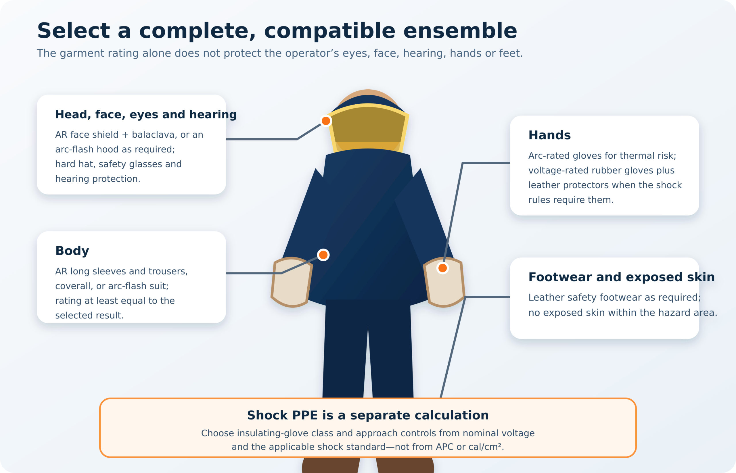
At minimum, resolve these components:
- Body: AR shirt and trousers, coverall, coat/trouser combination or suit with sleeves secured, collar closed and shirt tucked when designed that way. No exposed skin in the hazard area.
- Head and face: hard hat; AR face shield with adequate wraparound protection and AR balaclava where required, or a full arc-flash hood. For incident energy above 12 cal/cm², NFPA’s incident-energy method requires an arc-flash suit hood.
- Eyes: safety glasses or goggles remain required under a shield or hood because the shield is not primary eye protection.
- Hearing: insert-type hearing protection is commonly required inside the arc-flash boundary; arc pressure and sound are separate hazards.
- Hands: arc-rated gloves for thermal exposure. When shock exposure exists, use voltage-rated rubber insulating gloves with leather protectors and testing/inspection appropriate to the voltage and standard. Confirm the thermal performance of the combination.
- Feet: leather safety footwear where required and appropriate footwear for the workplace. Do not assume an EH marking makes a boot an arc-rated substitute for all other controls.
Step 7 — Inspect, don and use it correctly
Before entry into the hazard area:
- inspect for holes, tears, contamination, chemical damage, damaged closures and unauthorised repairs;
- verify that the label is readable and the rating/classes match the permit or job briefing;
- confirm hood lens condition, airflow/battery state where applicable, hard-hat attachment and hearing/eye protection;
- perform the required air test and inspection on insulating gloves, confirm test date and install leather protectors;
- remove conductive jewellery and secure tools;
- close the collar, cuffs and all fasteners; tuck garments as the manufacturer instructs; and
- ensure the worker can see, hear instructions, operate the mechanism and escape without removing PPE.
Cleaning must follow the manufacturer’s instructions. Fabric softeners, chlorine bleach, uncontrolled industrial laundering and contamination by flammable liquids can degrade performance. Never modify a hood, drill ventilation holes or attach an unapproved camera, lamp or radio.
6. Practical calculation 1: estimate transformer-terminal fault current
This shortcut is useful for screening and checking a study—not for selecting PPE by itself.
For a transformer supplied from a stiff source, the approximate symmetrical three-phase short-circuit current at its LV terminals is:
where:
- ST = transformer rating in VA;
- ULL = secondary line-to-line voltage in V; and
- Zpu = transformer impedance in per unit, so 6% becomes 0.06.
Worked example: 1,000 kVA, 400 V, 6% transformer
-
Rated secondary current:
Irated = 1,000,000 ÷ (√3 × 400) = 1,443 A -
Approximate terminal short-circuit current:
Ik ≈ 1,443 ÷ 0.06 = 24,050 A ≈ 24.1 kA
This does not mean “24 kA requires APC 2” or “24 kA equals Category 4.” Incident energy still depends strongly on the arc model, breaker/fuse clearing time, enclosure and distance. A real study also includes upstream-source impedance, transformer tolerance, cables/busway, motor and generator contribution, operating modes and maximum/minimum cases.
7. Practical calculation 2: DGUV box-test selection
DGUV Information 203-077 compares the energy expected from the installation with the protective level represented by APC 1 or APC 2.
7.1 Core variables and equations
For AC systems, a conservative estimate of arc current is:
where I″k3,min is the minimum initial symmetrical three-phase short-circuit current and kB is an arc-current factor. DGUV permits a conservative kB = 0.5 for many low-voltage cases; for medium/high voltage the simplified factor is generally 1.0. Use the detailed method where necessary.
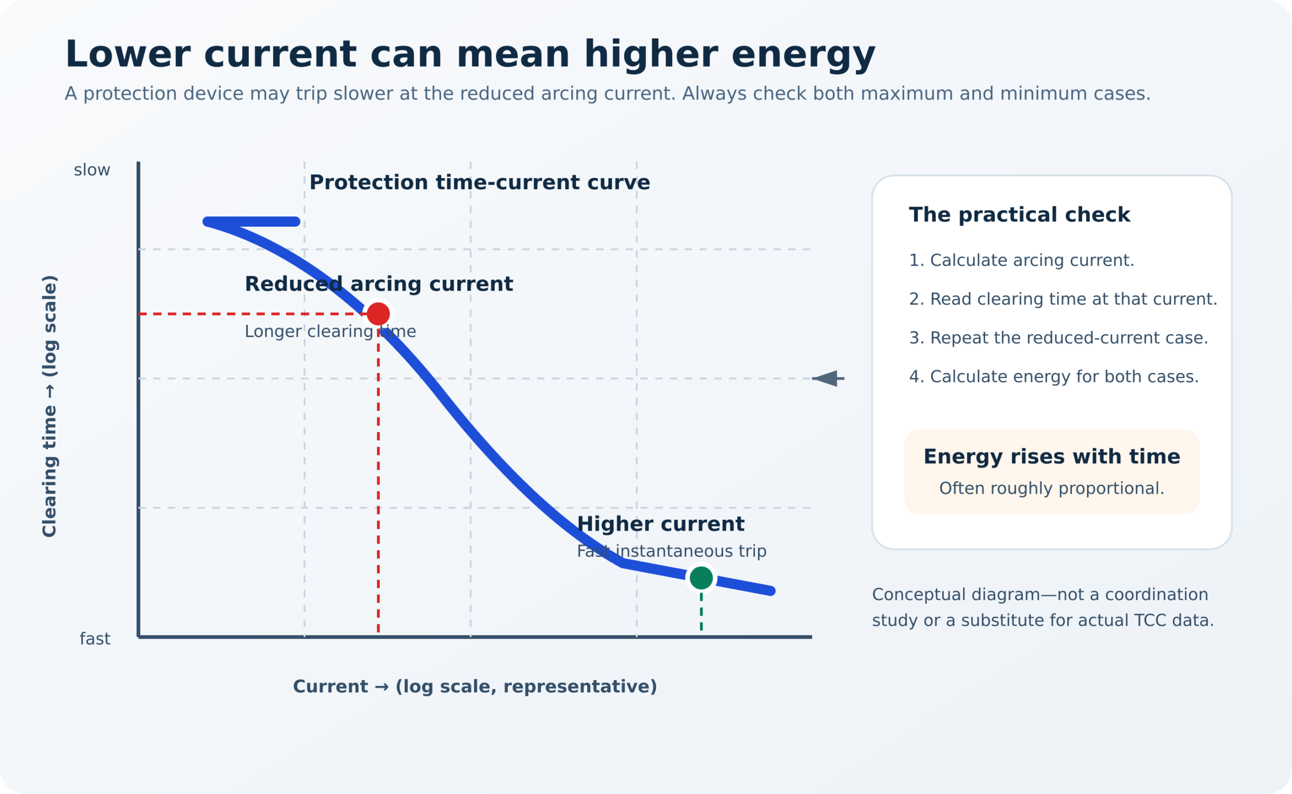
Read the total clearing time tk from the protective device’s time-current characteristic at IkLB, not at the bolted fault current. Include relay time, breaker opening time and any intentional delay.
The expected arc energy can be expressed as:
with:
Here kP converts short-circuit power to arc power and depends on voltage, conductor gap and R/X ratio. DGUV provides the required tables and detailed expressions; do not invent a value from voltage alone.
For IEC box-tested PPE, the protection level at the work point is:
where:
- a = working distance, valid in this method for a ≥ 300 mm;
- kT = transmission/geometry factor; DGUV commonly uses about 1.0 for a small box, 1.5–1.9 for larger/rear-wall configurations and 2.4 for an open-arc configuration; and
- WLBP = reference test energy: approximately 168 kJ for APC 1 or 320 kJ for APC 2.
Selection condition:
This distance-squared expression belongs specifically to the DGUV box-test comparison. It must not be copied into an IEEE 1584 calculation.
7.2 Fully worked DGUV low-voltage example
The following reproduces the logic of the official DGUV industrial LV example in an audit-friendly form.
Given
| Input | Value |
|---|---|
| Nominal voltage | 400 V |
| Conductor gap | 20 mm |
| Maximum three-phase short-circuit current | 16.4 kA |
| Minimum three-phase short-circuit current | 14.7 kA |
| R/X ratio | 0.81 |
| Working distance | 300 mm |
| Geometry factor for the assessed enclosure | 1.5 |
Step A — Conservative arc current
Step B — Clearing time
At about 7.4 kA, the protective-device characteristic in the example gives:
This is why the actual time-current curve matters. Using the time at 16.4 kA could produce an unjustifiably short duration.
Step C — Short-circuit power
Step D — Arc power and energy
Using the conservative example coefficient kP ≈ 0.30 for the assessed geometry:
Rounding and the detailed official coefficients give approximately 45.2 kJ in the DGUV example.
Step E — Compare with APC protection levels
At 300 mm and kT = 1.5:
Since 45.2 kJ ≤ 252 kJ, APC 1 is sufficient for that assessed task and geometry. A more exact calculation in the DGUV example produces an even lower expected energy (about 19.1 kJ), but DGUV still recommends APC 1 as a practical protective level.
What the example does not prove: it does not approve every task at that switchboard. Opening an enclosure, changing distance, changing protection settings, removing current-limiting fuses or working on a different compartment requires a new task-specific assessment.
8. Practical calculation 3: IEEE 1584 incident energy
Related engineering guide: Arc-Flash Calculation and Risk Reduction for MV Switchgear.
IEEE 1584-2018 is a multi-stage empirical model. It is not responsible practice to copy a single formula from the obsolete 2002 edition into a spreadsheet and call the result compliant. Use validated, version-controlled software or the official IEEE resources, retain inputs and document the protective-device curve used.
8.1 Scope
IEEE 1584-2018 covers calculation of incident energy and arc-flash boundary for three-phase AC systems from 208 V through 15 kV within its stated data/model limits. It does not itself select PPE or cover every single-phase, DC or above-15-kV case. For those systems, use another recognised engineering method suitable for the installation.
8.2 Minimum data set
Collect and verify:
- one-line diagram, utility/source data and every normal/emergency operating mode;
- transformer ratings, impedances and tap positions;
- conductor and busway lengths, sizes and configurations;
- generator and motor contributions;
- nominal voltage and maximum/minimum bolted fault current;
- conductor gap;
- enclosure height, width and depth;
- electrode configuration: VCB, VCBB, HCB, VOA or HOA as applicable;
- working distance for the exact task;
- breaker, relay and fuse settings plus manufacturer time-current curves; and
- maximum and reduced arcing-current cases.
8.3 Calculation sequence
- Calculate bolted fault current for all credible operating modes.
- Calculate arcing current with the IEEE 1584 model for voltage, gap and electrode configuration.
- Determine protective-device clearing time at the calculated arcing current.
- Repeat the reduced arcing-current case required by the model; it can move the device out of its instantaneous region.
- Calculate incident energy at the stated working distance, including enclosure correction.
- Calculate the arc-flash boundary—the distance at which the incident energy falls to 1.2 cal/cm² (5 J/cm²).
- Select a complete AR ensemble with rating at least equal to the calculated incident energy, subject to the governing standard and employer margin.
- Put the applicable data on the label and control it through management of change.
8.4 Simple PPE selection from a completed study
Suppose a validated study and current label state:
- incident energy: 7.2 cal/cm²;
- working distance: 455 mm (18 in);
- arc-flash boundary: 1.4 m; and
- nominal voltage: 480 V.
Under the incident-energy method, choose a complete ensemble with an arc rating of at least 7.2 cal/cm². In practice, a tested 8 cal/cm² or higher system is a common next available rating. Do not relabel the result “Category 2”; Category 2 belongs to the separate NFPA table method.
The full system still includes the head/face configuration required for the energy range, eye and hearing protection, appropriate hand protection and shock PPE based on voltage and exposure. If the actual face or hands will be closer than 455 mm, the engineer must address that distance; the 7.2 cal/cm² torso value is not automatically valid there.
8.5 Useful sensitivity checks—and their limits
- Clearing time: within the same model conditions, incident energy often changes approximately in proportion to arc duration. If an event is 8 cal/cm² at 0.20 s, a genuine reduction to 0.10 s may screen near 4 cal/cm². Recalculate formally because arcing current, current-limiting behaviour and device operation may change.
- Distance: never apply a generic inverse-square rule to enclosed low-voltage switchgear. IEEE 1584 uses configuration-specific distance exponents and enclosure corrections.
- Current: more current can mean more power, but a lower current may create a much longer clearing time. Calculate both cases.
- Settings: maintenance-mode or zone-selective-interlocking changes can reduce duration, but only when enabled, tested, documented and included in the work procedure.
9. What should the operator actually wear?
9.1 When the result is an IEC box-test class
| Assessed result | Body system | Head/face/hands | Critical checks |
|---|---|---|---|
| APC 1 | Complete IEC 61482-2 garment or tested combination marked APC 1 or APC 2 | Components selected for the same assessed hazard; face protection meeting the applicable arc standard; shock gloves separately | Whole-garment certification, closures, coverage, distance and compatibility |
| APC 2 | Complete IEC 61482-2 garment or tested combination marked APC 2 | APC 2-compatible head/face solution where required; hand and shock protection selected separately | Do not assume every component of an “APC 2 kit” has the same open-arc number; verify each label and system data |
| Expected energy exceeds APC 2 protection level | Do not invent APC 3 | Reduce energy, increase remote distance, change task/protection or use an engineering assessment and suitable open-arc-rated system if permitted |
9.2 When the result is calculated incident energy
| Incident-energy result | Clothing principle | Head/face principle under NFPA incident-energy method |
|---|---|---|
| Below 1.2 cal/cm² | Below the conventional arc-flash boundary threshold; other site clothing and hazards still govern | Shock, eye, hearing, task and local-rule requirements can still apply |
| 1.2–4 cal/cm² | AR clothing system rated at least to the calculated value | AR face shield plus AR balaclava, or AR hood, as required by the current table/assessment |
| Above 4–8 cal/cm² | AR system rated at least to the calculated value; an 8 cal system is common only when it meets/exceeds the result | Same complete-component rule; do not omit safety glasses or hearing protection |
| Above 8–12 cal/cm² | AR system rated at least to the result; no exposed skin | AR face shield plus AR balaclava, or AR hood, as specified |
| Above 12 cal/cm² | AR suit/ensemble rated at least to the result | Arc-flash suit hood required by NFPA’s incident-energy method |
| Above 40 cal/cm² | Engineering review; prioritise de-energisation, faster protection, remote operation and exposure reduction | Not “Category 5”; any justified task needs a specific approved solution |
The thresholds in this table are not a substitute for the current NFPA tables. The arc rating must always meet the actual calculated value, not merely the top of a convenient band.
10. Internal-arc-classified and arc-resistant switchgear
Related guide: Why Internal Arc Classification Is Not an Arc-Flash Risk Assessment.
Metal-enclosed switchgear tested to IEC 62271-200 may carry an IAC designation. North American arc-resistant switchgear is evaluated under IEEE C37.20.7. These designs can route hot gases and particles away from personnel when the equipment is installed and used exactly as tested.
IAC or arc-resistant construction can materially reduce risk during closed-door operation, but it does not automatically remove the arc-flash hazard because:
- the rating applies only to the tested sides, current, duration and installation arrangement;
- pressure-relief ducts, ceiling clearance, room volume and exhaust path must match the design;
- all doors, covers, vents and fasteners must be closed and secured;
- racking, open-door work, cable-compartment access and maintenance may be outside the tested configuration;
- ageing, contamination, modifications and defeated interlocks can invalidate assumptions; and
- the test addresses accessibility criteria, not garment selection for every task.
Record the IAC/arc-resistant designation in the risk assessment, but do not translate it into APC 1, APC 2 or an NFPA category.
11. Representative manufacturers and product families
The table below is a market orientation, not an endorsement or approved-vendor list. Product availability, certification and model data change. Verify the current garment label, data sheet, EU declaration of conformity where applicable, and compatibility of the complete ensemble before purchase.
| Manufacturer / region | Representative official product or range | Published rating example | Best fit / purchasing note |
|---|---|---|---|
| DEHNcare, Germany | ArcFit HLP 63 | HLP 63: APC 2, ATPV 63 cal/cm², ELIM 58 cal/cm² | High-protection IEC ensemble; verify hood, gloves and garment as the intended system |
| BSD, Germany | FuturaTec protective suit | APC 2; ATPV 39 cal/cm²; ELIM 33 cal/cm² | IEC box-test plus open-arc information; check exact model and size range |
| ProGARM, Europe/UK | Broad arc-flash garment range | Manufacturer states garments are tested by open-arc and box-test methods; values vary by model | Useful for daily-wear/layered programmes; specify exact tested combination |
| Tranemo, Sweden | Arc-rated workwear and layered systems | Examples include APC 1 garments and APC 2 garments with ELIM/EBT values | Strong daily-wear and layering options; do not add layer ratings unless tested together |
| CATU, France | Arc-flash garment and kit ranges | Official examples include APC 1 / 12 cal and APC 2 / 25–40 cal products | Integrated kits; verify each kit component and the exact standards edition |
| Sioen PRO, Belgium | Talsi arc-protective rain jacket | APC 2; ATPV 28 cal/cm² | Weather/rain protection; confirm trousers, hood and underlying system as a combination |
| Honeywell Salisbury, United States | Pro-Wear Plus garments and kits | 40 cal/cm² suit options | Established NFPA/ASTM-style suit kits; confirm fan/hood configuration and system rating |
| Oberon, United States | CAT 40 suit and hood sets | 40 cal/cm² systems | Category 4 table-method or ≥40-cal incident-energy applications when otherwise justified |
| National Safety Apparel / Enespro, United States | Arc-flash daily wear and suit kits | 40 cal/cm² kit options | Integrated US-market systems; check hood visibility, ventilation and glove interfaces |
How to compare quotations fairly
Require every bidder to state:
- exact manufacturer, model, fabric and size range;
- exact standard and edition on the garment label;
- APC class and/or ELIM, ATPV, EBT/arc rating—without vendor-created conversions;
- whether the value applies to material, garment or complete ensemble;
- test report/certificate and, in the EU/EEA, CE documentation and declaration of conformity;
- hood lens rating, visible-light transmission, anti-fog performance and field of view;
- glove standard/class, protector glove and test interval;
- laundering, repair, inspection and retirement criteria;
- replacement parts and lead time; and
- a wearer trial covering mobility, reach, visibility, hearing, heat stress and escape.
12. Common mistakes that cause wrong PPE selection
- Selecting by voltage: a 400 V board with slow protection can have more incident energy than a well-protected 11 kV board.
- Using bolted fault current as the box-test class: 7 kA at the bus does not mean APC 2, and 20 kA does not automatically exceed APC 2.
- Converting APC 2 to 40 cal/cm²: there is no universal conversion.
- Reading clearing time at bolted current: the arc current is lower and may put the breaker in a slower region.
- Ignoring the reduced-current case: lower current can produce higher energy through a longer duration.
- Assuming closed doors eliminate risk: normal-condition criteria and the specific task still matter.
- Treating IAC as a PPE class: IAC describes tested switchgear accessibility, not a garment.
- Adding garment ratings: two 8-cal layers do not become 16 cal unless the exact system has been tested and assigned that rating.
- Buying a high-calorie coat but leaving the face/hands unprotected: the ensemble is limited by its weakest exposed component.
- Using a stale label: transformer, source, settings or operating-mode changes can invalidate it.
- Removing the hood to see or breathe: solve visibility and heat-stress problems before the task; do not defeat PPE inside the boundary.
- Believing PPE makes energized work safe: it reduces burn injury probability; it cannot guarantee survival or address every arc-blast consequence.
13. Commissioning and annual programme checklist
Engineering controls
Study and labels
PPE programme
The 2027 edition of NFPA 70E also introduced a two-person requirement for certain justified energized work where the employee is exposed to specified electrical hazards; see NFPA’s official explanation of the additional-person requirement. Apply the exact rule and local law rather than a simplified interpretation.
14. Frequently asked questions
What PPE class is required for 400 V switchgear?
There is no universal class. Some low-energy tasks may require no special arc-flash garment beyond prescribed workwear; other 400/480 V boards can exceed 40 cal/cm² because of high current and slow clearing. Use the task-specific DGUV, IEEE 1584 or applicable assessment.
What PPE class is required for 11 kV or 33 kV switchgear?
Again, voltage alone is insufficient. IEEE 1584-2018 covers applicable three-phase AC calculations only through 15 kV; 33 kV requires another validated engineering method. IAC switchgear, remote operation, protection time, working distance and task can dominate the result.
Is APC 2 better than APC 1?
APC 2 passes a more severe IEC box test, but “better” is not a complete selection rule. APC 1 is appropriate where the assessed protection level is sufficient and may be lighter and more wearable. The safest garment is the compliant system that workers can wear correctly for the task; unnecessary bulk can reduce visibility, mobility and compliance.
Does a 40 cal suit protect against every switchgear arc?
No. The rating addresses thermal exposure up to the tested arc rating. It is not a guarantee against pressure, projectiles, shock, hot oil or energy above the rating. It also cannot justify the task.
Can I wear cotton under an arc-flash suit?
Only according to the garment/system instructions and governing standard. Non-melting natural-fibre underlayers may be allowed in some systems, but an untested underlayer adds no claimed arc rating and may ignite if the outer layer breaks open. Meltable synthetic underlayers are generally prohibited unless specifically part of a tested system.
Is an arc-rated face shield enough above 12 cal/cm²?
Under the NFPA incident-energy method, an arc-flash suit hood is required above 12 cal/cm². IEC/DGUV programmes must follow their applicable head/face assessment and the component’s certification.
Do voltage-rated gloves also provide arc-flash protection?
Rubber insulating gloves are selected for shock voltage and are normally worn with leather protectors. Their combination may provide some thermal protection, but arc performance must be verified for the product/system and task. Do not infer an arc rating from the glove voltage class.
Can an operator stand outside the arc-flash boundary and operate remotely without arc PPE?
Remote operation outside the calculated boundary is a strong engineering control. The operator still needs protection for other hazards and the remote position must not be in the pressure/exhaust path. The site risk assessment makes the final determination.
Conclusion
Correct switchgear PPE selection is an engineering and work-planning decision, not a voltage lookup. The safest sequence is:
- de-energize and verify whenever possible;
- define the exact task and equipment condition;
- use a current study and label;
- stay within one recognised selection method;
- calculate arcing current and clearing time correctly—including the reduced-current case;
- choose a complete, compatible ensemble; and
- reduce the hazard with protection, maintenance and remote operation instead of relying on heavier clothing.
If one sentence is retained from this guide, it should be this: APC 1/APC 2, ATPV/EBT/ELIM and NFPA Categories 1–4 are different rating languages; use the language produced by the risk assessment and never convert them by guesswork.