

Polarity is not a cosmetic marking on a polarized DC miniature circuit breaker. It is part of the breaker’s interruption design. Connecting a polarized DC MCB in the wrong direction may allow its thermal or magnetic trip mechanism to operate while preventing the arc-control system from extinguishing the fault current safely.
The most confusing point is that the + and − signs printed beside the terminals are not simply permanent labels for the positive and negative system conductors. On a closed pole, both terminals are on the same conductor and are therefore at almost the same potential. The markings indicate the polarity that must appear across that pole when it opens, and consequently the required direction of conventional current through its arc chamber.
This distinction explains a seemingly strange but correct arrangement found on some two-pole DC MCBs: with the supply connected at the upper terminals, terminal 1 is connected to system negative while terminal 3 is connected to system positive. That layout is intentional—not a manufacturing or schematic error.
Essential rule: Never infer the wiring from terminal numbers, customary AC practice, or another breaker family. Use the exact wiring diagram for the complete manufacturer, series, pole count, voltage, grounding arrangement, and direction of possible fault current.
Why interrupting DC is more difficult than interrupting AC
When circuit-breaker contacts separate under load or fault current, the current does not stop instantly. An electric arc forms between the contacts.
In an AC circuit, current passes through a natural zero twice per cycle. At 50 Hz, a natural current zero occurs every 10 ms. A correctly designed AC breaker uses this zero crossing to de-ionize the contact gap and prevent the arc from reigniting.
Steady DC has no periodic natural current zero. The breaker must force the current to zero by increasing arc voltage and removing energy from the arc. A DC MCB may use several coordinated features:
- rapid contact separation;
- an arc runner that moves the arc away from the contacts;
- splitter plates that divide, lengthen, cool, and de-ionize the arc;
- a magnetic field that drives the arc into the arc chute; and
- sufficient contact gap and insulation for the declared DC recovery voltage.
In many compact polarized DC MCBs, permanent magnets assist the magnetic blow-out action. The force acting on the arc depends on the direction of current relative to the permanent magnetic field. Correct polarity drives the arc toward the chute. Reversed polarity can drive it in the wrong direction.
ABB’s technical literature for comparable S200/S400 DC families states that permanent magnets are fitted around the arc chutes, that polarity must be respected, and that incorrect polarity may damage the MCB. The same document specifies that, for the illustrated top-fed two-pole arrangement, terminal 1 is connected to − and terminal 3 to +.
Polarized, non-polarized, and AC-only breakers are not interchangeable
| Device type | What the marking means | Permitted current direction | Design implication |
|---|---|---|---|
| Polarized DC MCB | Usually carries + and − terminal markings and a product-specific diagram |
Only the direction or circuit arrangements explicitly declared by the manufacturer | Reversing the fault-current direction can compromise arc transfer and interruption |
| Non-polarized or bidirectional DC MCB | Manufacturer explicitly declares polarity-independent or bidirectional DC operation | Both directions, within the declared voltage, current, breaking capacity, and wiring rules | Suitable where current or energy flow can reverse, provided all other ratings are met |
| AC MCB with a declared DC rating | The data sheet gives a specific DC voltage and pole arrangement | Only as stated in its DC application instructions | Its DC rating is often lower than its AC rating |
| AC-only MCB | No DC utilization rating is declared | Not suitable for DC interruption | Never assume that an AC voltage or kA rating remains valid on DC |
Not every breaker that can carry DC is polarity-sensitive, and not every product with identical external dimensions has the same internal arc system. The decisive evidence is the manufacturer’s current data sheet and the markings on the exact device.
How to interpret the + and − marks correctly
For the ABB SB200 DC arrangements shown below, conventional current passes through each interrupting pole from the terminal marked + toward the terminal marked −.
That does not mean one end of a closed pole is the positive system conductor and the other end is the negative system conductor. Consider a single pole installed in the positive conductor: while the breaker is closed, both ends of that pole are positive relative to system negative. The + and − marks define the required arc polarity and current direction when the contacts separate.
This is why all four items must be kept separate during design review:
- System conductor polarity: positive or negative conductor.
- Breaker terminal marking: the
+or−printed beside a terminal. - Terminal number: for example 1, 2, 3, or 4.
- Source/load position: whether the supply enters from above or below.
Terminal numbering alone is not proof of a mandatory line side. In the supplied ABB diagrams, terminals 1 and 3 are used as supply terminals in one approved arrangement, while terminals 2 and 4 are used as supply terminals in another.
ABB SB200 DC case study
The following manufacturer page combines the permissible-voltage layouts with the one- and two-pole supply/load diagrams. It is useful as an overview, but the enlarged figures that follow are easier to read during panel design or commissioning.
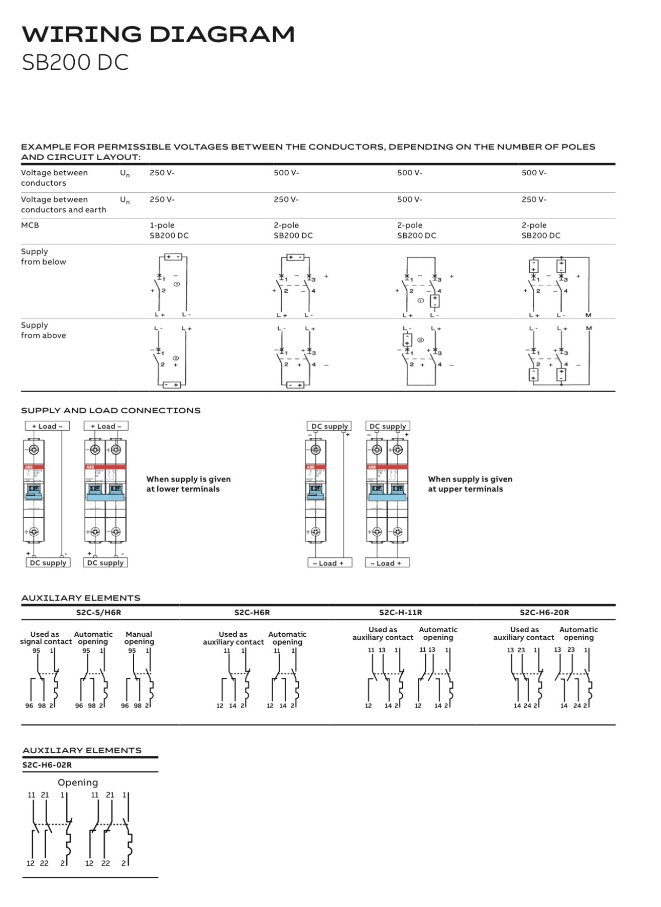
Figure 1 — Full ABB SB200 DC wiring page. Image credit: ABB; source image supplied for this article.
Permissible voltage depends on pole count and circuit topology
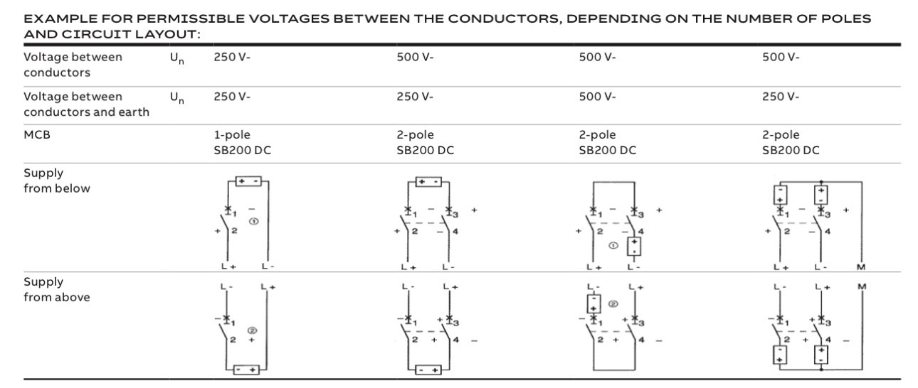
Figure 2 — The rated voltage cannot be selected from pole count alone. The manufacturer also distinguishes voltage between conductors, voltage from conductor to earth, grounding topology, and the exact pole arrangement.
In the shown SB200 DC table, the example ratings include 250 V DC for a one-pole arrangement and 500 V DC for specified two-pole arrangements. However, the table also shows that a 500 V conductor-to-conductor system may be limited to 250 V conductor-to-earth in some layouts, while a different arrangement permits 500 V conductor-to-earth.
This distinction is critical. A breaker may be capable of interrupting the total loop voltage using two simultaneously opening poles, yet each pole and its insulation system still sees a voltage determined by the earthing arrangement and fault location. A midpoint-earthed ±250 V system, a 500 V floating system, and a 500 V system with one conductor earthed are not automatically equivalent applications.
Do not obtain a higher DC voltage rating merely by placing arbitrary poles in series. The manufacturer must declare the exact pole connection, simultaneous opening arrangement, voltage between conductors, voltage to earth, and short-circuit rating for that topology.
Supply connected at the lower terminals
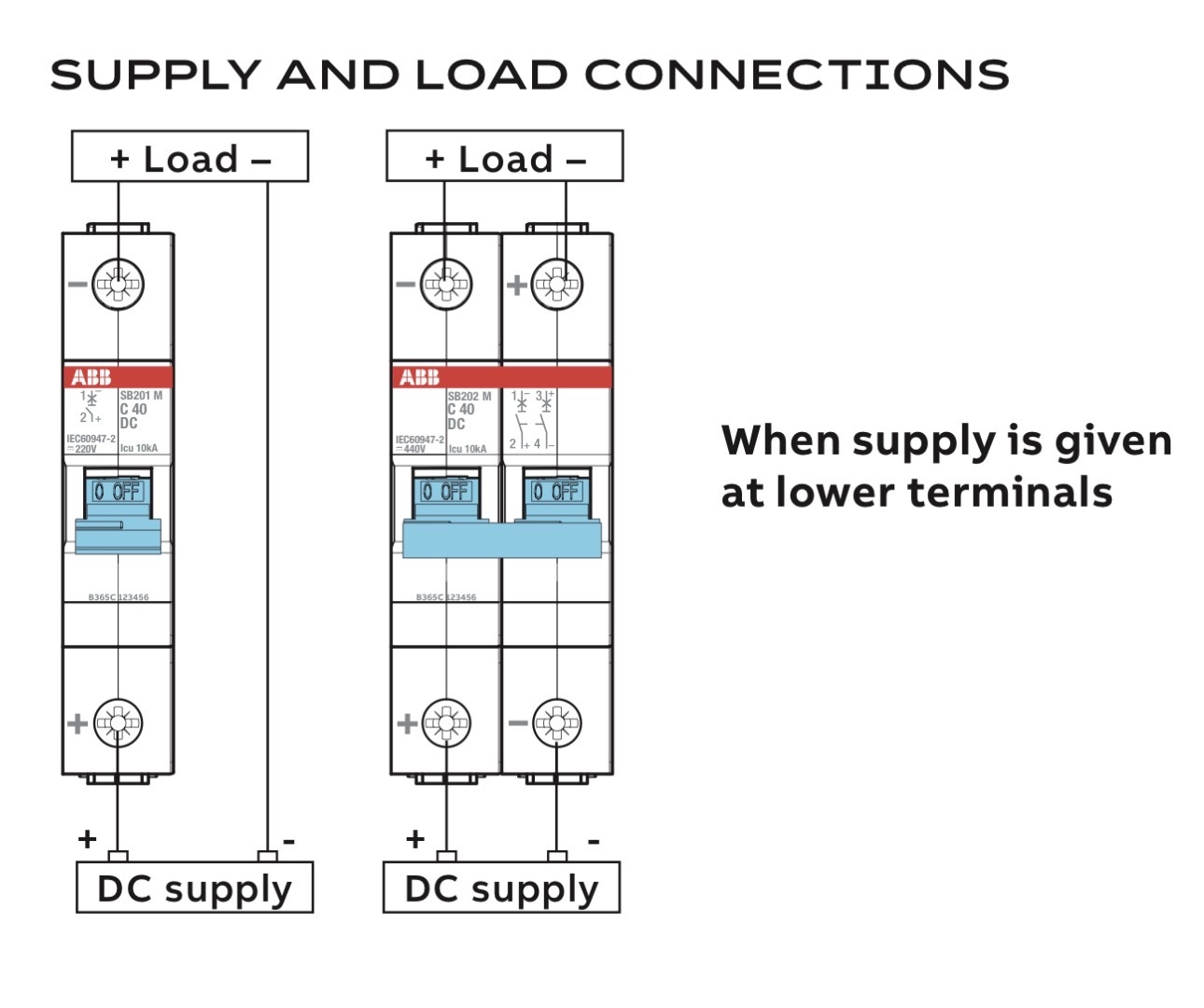
Figure 3 — ABB SB200 DC connection examples with the supply at the lower terminals.
For the illustrated one-pole arrangement:
- source positive connects to lower terminal 2, which is marked
+; - load positive leaves upper terminal 1, which is marked
−; and - the negative conductor bypasses the MCB.
Conventional current therefore travels through the pole from terminal 2 (+) toward terminal 1 (−). Notice that terminal 1 is still connected to the positive load conductor even though the breaker terminal is marked −. This proves why the device marking must not be confused with the steady-state polarity of the external conductor.
For the illustrated two-pole arrangement:
- source positive connects to lower terminal 2;
- source negative connects to lower terminal 4;
- load positive leaves upper terminal 1; and
- load negative leaves upper terminal 3.
The positive-side pole carries conventional current from terminal 2 (+) to terminal 1 (−). After passing through the load, the return current enters terminal 3 (+) and leaves terminal 4 (−). Both poles therefore see the current direction required by their magnetic arc systems.
Supply connected at the upper terminals
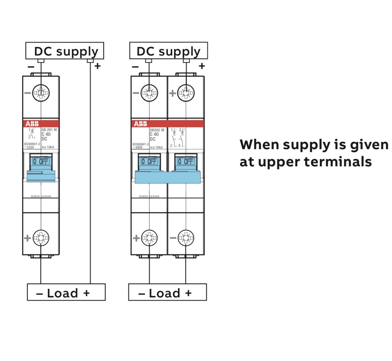
Figure 4 — ABB SB200 DC connection examples with the supply at the upper terminals.
For the illustrated one-pole arrangement:
- source negative connects to upper terminal 1, which is marked
−; - load negative leaves lower terminal 2, which is marked
+; and - the positive conductor bypasses the MCB.
The conventional return current flows from the load through terminal 2 (+) toward source negative at terminal 1 (−). Therefore, simply moving the same positive-conductor connection from the bottom to the top would not reproduce this approved arrangement.
For the illustrated two-pole arrangement:
- source negative connects to upper terminal 1;
- source positive connects to upper terminal 3;
- load negative leaves lower terminal 2; and
- load positive leaves lower terminal 4.
This is the reason a correctly connected top-fed two-pole breaker can show − at terminal 1 and + at terminal 3. The positive-side current passes from terminal 3 (+) to terminal 4 (−), then through the load. The return current passes from terminal 2 (+) to terminal 1 (−). Again, both arc chambers receive the intended current direction.
Connection summary for the illustrated ABB diagrams
| Arrangement | Source connections | Load connections | Bypassed conductor |
|---|---|---|---|
| Lower-fed, 1 pole | + source → terminal 2 |
terminal 1 → + load |
Negative |
| Upper-fed, 1 pole | − source → terminal 1 |
terminal 2 → − load |
Positive |
| Lower-fed, 2 poles | + source → 2; − source → 4 |
1 → + load; 3 → − load |
None |
| Upper-fed, 2 poles | − source → 1; + source → 3 |
2 → − load; 4 → + load |
None |
Product-specific warning: This table explains only the supplied ABB SB200 DC figures. Do not transfer it to another ABB family—or to a Siemens, Schneider Electric, Eaton, or other manufacturer’s breaker—without confirming that product’s own instructions.
Can a polarized DC MCB be supplied from either the top or the bottom?
Sometimes, but this statement is easy to misuse.
The supplied ABB diagrams provide valid arrangements for both upper and lower supply entry. They do not authorize the installer to swap line and load while leaving every conductor in the same left/right position. When the supply side changes, the system-polarity placement and, in the one-pole example, the protected conductor also change so that current still travels through each pole in the approved direction.
A safe conclusion is therefore:
Top or bottom feed is permitted only when the exact product documentation shows the complete connection arrangement being used.
If a design requires the positive conductor to be protected by a one-pole breaker and the source cable must enter from above, select a manufacturer-approved wiring arrangement or a suitable non-polarized device. Do not improvise by ignoring the terminal marks.
What can happen if polarity is reversed?
The overload element and magnetic instantaneous release may still detect overcurrent because their basic sensing action is not necessarily dependent on current direction. This can create a dangerous false impression: the handle may trip, yet the breaker’s interruption performance may no longer match its tested rating.
Possible consequences include:
- the arc being forced away from the intended arc runner or splitter stack;
- longer arcing time and greater arc energy;
- accelerated erosion or welding of contacts;
- damage to insulation or the breaker enclosure;
- failure to interrupt the prospective DC fault current; and
- fire, hot-gas emission, or damage to adjacent equipment.
The severity depends on system voltage, prospective short-circuit current, circuit inductance, clearing time, enclosure, and breaker construction. Correct operation during a low-current bench check does not prove safe interruption at rated short-circuit duty.
Never perform an improvised short-circuit test to “check” polarity. DC breaking-capacity verification belongs in an accredited test setup using the manufacturer’s declared test conditions.
Bidirectional systems need special attention
Current direction may reverse in systems such as:
- batteries that both charge and discharge;
- bidirectional battery energy storage converters;
- regenerative DC drives;
- UPS battery circuits;
- parallel photovoltaic strings during certain faults;
- DC bus ties with multiple sources; and
- converters that can feed a fault from either side.
A polarized MCB is acceptable in such a system only if the manufacturer explicitly rates the device and the proposed pole arrangement for every credible direction of fault current. Normal power-flow direction is not enough; the engineer must examine fault contribution from all sources.
Where the direction can reverse, use a breaker explicitly declared as non-polarized, polarity-independent, bidirectional, or approved for a documented voltage-reversal scheme. Confirm that the declaration applies to interruption—not merely current carrying—and to the actual DC voltage and fault level.
Engineering selection checklist
Before selecting a DC MCB, verify all of the following:
| Check | Required evidence |
|---|---|
| Exact device identity | Manufacturer, complete type code, number of poles, curve, rated current, and current revision of the data sheet |
| DC operational voltage | Declared Ue for the exact pole arrangement—not the AC rating, insulation voltage, or impulse voltage |
| Voltage to earth | Maximum credible conductor-to-earth voltage for normal operation and first-earth-fault conditions |
| System earthing | Floating/IT, midpoint-earthed, positive-earthed, or negative-earthed topology |
| Breaking capacity | Icn, Icu, Ics, or other applicable declared DC short-circuit rating at the system voltage |
| Prospective fault current | Contribution from batteries, rectifiers, PV strings, capacitors, and every parallel source |
| Fault-current direction | All credible directions during charging, discharging, regeneration, backfeed, and earth faults |
| Circuit inductance | Manufacturer’s declared DC application limits and time-constant conditions where specified |
| Number and connection of poles | Exact manufacturer diagram, common trip/opening, and required all-pole isolation |
| Feed direction and polarity | Terminal marks and approved upper/lower source arrangement |
| Temperature and grouping | Ambient-temperature correction, adjacent-device derating, conductor size, and terminal torque |
| Isolation function | Whether the selected product is declared suitable for isolation and whether all live conductors must be opened |
| Product standard | Appropriate marking/certification for the installation, such as IEC 60898-3 or IEC 60947-2 |
The breaker’s rated current and trip curve are only part of the selection. A 10 kA AC marking does not establish 10 kA DC interruption, and a 500 V insulation rating does not establish a 500 V DC operational breaking rating.
Installation and commissioning procedure
Only electrically skilled persons should work on these circuits. Apply the site’s lockout/tagout and absence-of-voltage procedure before touching conductors.
- Record the exact MCB type code and photograph all terminal markings.
- Obtain the current manufacturer data sheet for that exact code.
- Mark the physical source side and identify every possible backfeed source.
- Verify system positive, negative, and earth with an appropriately rated test instrument.
- Compare the proposed circuit conductor by conductor with the manufacturer’s diagram.
- Confirm voltage between conductors and maximum voltage from each conductor to earth.
- Confirm the DC short-circuit rating exceeds the calculated prospective fault current.
- Check that each pole sees the manufacturer-approved current direction for every credible fault.
- Verify conductor cross-section, stripping length, terminal torque, temperature limits, and grouping derating.
- Apply clear panel labels showing source position and polarity; do not rely only on wire colour.
- Complete dead tests and the manufacturer-approved functional checks.
- After controlled energization, verify polarity and voltage at the breaker terminals without creating a fault.
If any required diagram or rating is unavailable, do not energize the circuit on the basis of similarity to another MCB.
Common mistakes
| Mistake | Why it is wrong | Correct action |
|---|---|---|
| “Terminal 1 is always line and terminal 2 is always load.” | The supplied manufacturer diagram permits different supply sides and changes the polarity layout accordingly. | Follow the exact DC wiring diagram. |
| “The plus mark must always connect to the positive cable.” | A load-side terminal on the negative conductor can be marked + because the mark defines arc polarity across the opening pole. |
Distinguish device terminal marking from system conductor polarity. |
| “If it trips, it is wired correctly.” | The release can operate even when interruption performance is compromised. | Verify polarity and breaking duty from documentation. |
| “Two poles automatically double the DC voltage rating.” | Voltage sharing depends on the tested circuit arrangement and system grounding. | Use only the declared pole topology and ratings. |
| “Any AC MCB can be derated for DC.” | DC interruption requires a declared DC utilization rating and test evidence. | Select a breaker with an explicit DC rating. |
| “Normal current only flows one way, so polarity is fixed.” | Fault current may be supplied from a charger, battery, PV string, capacitor, or parallel source in the opposite direction. | Analyse every credible fault-current contribution. |
Frequently asked questions
Are all DC MCBs polarized?
No. Some DC breakers are polarized because permanent magnets or an asymmetric arc path require a specific current direction. Others are explicitly designed and tested for polarity-independent or bidirectional operation. The product data—not appearance—decides.
Why does a top-fed two-pole breaker show terminal 1 as negative and terminal 3 as positive?
In the supplied ABB arrangement, this makes conventional current pass through both poles from each terminal marked + toward its corresponding terminal marked −. It allows both arc chambers to drive the arcs into their intended chutes. The apparently reversed left/right order is intentional.
Can I connect source positive to terminal 1 because terminal 1 is normally the line terminal?
Not on the illustrated top-fed polarized arrangement. ABB specifies terminal 1 as negative and terminal 3 as positive for that case. Terminal numbering does not override polarity instructions.
Can the ABB SB200 DC shown here be fed from below?
Yes, the supplied manufacturer page shows lower-fed arrangements. However, use the complete lower-fed layout: do not merely swap source and load on the upper-fed drawing.
Can I use a one-pole MCB only in the positive conductor?
Only when the product’s approved orientation and the system earthing/isolation requirements permit it. In the supplied ABB examples, the lower-fed one-pole arrangement interrupts the positive conductor, while the upper-fed one-pole arrangement interrupts the negative conductor. Many systems require all live conductors to be disconnected.
Is a polarized MCB suitable between a battery and a bidirectional inverter?
Not automatically. Charging, discharging, and fault backfeed can reverse current direction. Use the polarized device only if its manufacturer explicitly approves the complete arrangement for every credible interruption direction; otherwise select a suitably rated bidirectional DC protective device.
Final takeaway
The + and − symbols on a polarized DC MCB describe the required electrical orientation of its interruption system. They are not merely cable-polarity labels, and terminal numbers do not provide a universal substitute for the manufacturer’s DC wiring diagram.
For the ABB SB200 DC examples in this article, both upper and lower supply entry are possible—but only by following the corresponding complete arrangement. With a top-fed two-pole device, terminal 1 is negative and terminal 3 is positive by design. Reversing those connections may drive the DC arc away from the arc chute and invalidate the breaker’s tested interruption performance.
The safest engineering habit is simple: verify the exact breaker, fault-current direction, pole arrangement, voltage to earth, and DC breaking capacity before energization.
Technical references
- ABB, System pro M compact — Circuit Protection Devices on DIN Rail, particularly the DC application and polarity guidance for S200UDC/S200MUC.
- ABB, Low-voltage products and solutions for solar energy, examples of polarized and polarity-independent DC devices.
- IEC, IEC 60898-3:2019+A1:2022 — Circuit-breakers for DC operation.
- IEC, IEC 60898-2:2016 — Circuit-breakers for AC and DC operation.
- IEC, IEC 60947-2:2024 — Low-voltage switchgear and controlgear: Circuit-breakers.
- Siemens, 3VM for DC application, background on forcing a current zero during DC interruption.
Image credit: ABB. The four manufacturer-documentation images were supplied for this article. Product diagrams are reproduced for technical explanation; consult the latest official instructions for the exact device before design, installation, or commissioning.
Technical disclaimer: This article is educational and does not replace the device manufacturer’s instructions, a project-specific protection study, applicable installation rules, or work by a qualified electrical professional.