

G98, G99 and G100 are not three competing “certificates.” They perform different jobs in the Great Britain distribution-connection framework. G98 is the simplified route for small, fully type-tested microgeneration at low voltage. G99 is the principal connection code for generation that is outside G98. G100 specifies how a customer limitation scheme may control net export and/or import at the connection point. A project can—and often does—need both G99 and G100.
1. Current editions and geographical scope
As of the verification date of this article, the ENA catalogue identifies the following current Great Britain documents:
| Document | Current publication | Main purpose |
|---|---|---|
| EREC G98 | Issue 2, April 2026 | Fully type-tested microgenerators up to and including 16 A per phase, in parallel with public LV distribution networks. |
| EREC G99 | Issue 2, March 2025 | Type A–D power-generating modules connected in parallel with licensed DNO distribution networks in Great Britain. |
| EREC G100 | Issue 2, Amendment 2, April 2023; Issue 2 effective for new CLS applications from 1 May 2023 | Technical requirements for customer export and import limitation schemes. |
| G98 Forms / G99 Forms | Issue 1, April 2026 | Current application, installation and compliance forms. |
| G99 Standard Application Form | Issue 1, June 2025 | Standard information set for a G99 connection application. |
| Distributed Generation Connection Guide | EREP G98/99 Issue 3, March 2026 | Plain-language process guidance for connection customers. |
The official ENA G99 catalogue entry confirms that G99 Issue 2 is current and states its Great Britain scope. The ENA G98 catalogue entry identifies G98 Issue 2, and the ENA G100 overview explains the purpose and implementation date of G100 Issue 2.
Transmission-connected generation is another boundary. A plant connected to the transmission system, or a distribution project with material transmission-system interactions, can face the GB Grid Code, NESO processes, Bilateral Embedded Generation Agreements and DNO–transmission coordination in addition to distribution requirements. G99 alone is not a complete transmission connection specification.
2. Why these requirements exist
A distribution network was historically designed mainly for one-way power flow from a grid supply point to customers. Embedded generation and storage change fault current, voltage profile, reverse power flow, protection grading, system inertia and restoration behaviour. A generator that appears small at one site can become significant when thousands of units respond identically.
The requirements therefore address five system risks:
- Safety: a generator must not energise an islanded public circuit and endanger staff or the public.
- Power quality: voltage rise, rapid voltage change, flicker, harmonics and unbalance must remain acceptable.
- Protection and fault duty: the network must still detect and clear faults selectively, and switchgear fault ratings must not be exceeded.
- System stability: generators must ride through specified disturbances and provide predictable frequency/voltage behaviour instead of all disconnecting together.
- Capacity management: export or import may need to be capped where the network can accept the equipment but not its unrestricted simultaneous power flow.
These Engineering Recommendations are industry documents embedded in the distribution connection framework and reflected in connection agreements and DNO requirements. They are not optional marketing labels, and “the inverter has a UK setting” is not evidence that the whole installation complies.
3. The decision: G98, G99, G100—or a combination?
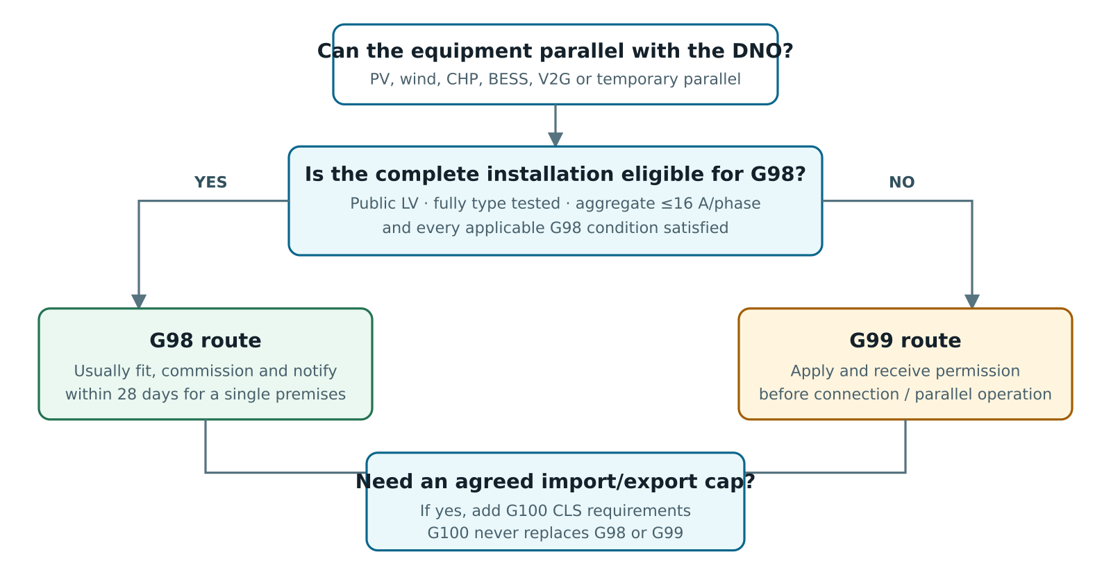
| Typical proposal | Likely route | Reason |
|---|---|---|
| 3.68 kW single-phase PV inverter, fully type tested, no other generation | G98 | At nominal 230 V, 16 A is approximately 3.68 kW per phase. For a single premises this is normally fit-and-notify. |
| 6 kW single-phase PV inverter | G99 Type A | It exceeds 16 A on that phase. Apply before connection. |
| Existing 3.68 kW PV plus separate 5 kW battery inverter | Usually G99 / SGI route possibly G100 | The aggregate parallel-capable plant exceeds the simple G98 envelope even if site export is limited. |
| 500 kW commercial PV + BESS with a 100 kW export cap | G99 Type A + G100 | G99 considers the installed generating module; G100 enforces the agreed net limit at the connection point. |
| Standby generator with mechanically/electrically interlocked break-before-make changeover | Not normally parallel generation | If parallel operation is impossible, the G98/G99 parallel-connection route may not apply. The DNO still needs confidence in the interlocking and earthing arrangement. |
| Standby generator with closed-transition transfer or periodic parallel testing | G99 | Even brief intentional parallel operation is relevant. G99 includes provisions for infrequent short-term parallel operation. |
| Vehicle-to-grid charger | G98 or G99 G100 if limited | When it exports, it behaves as generation; when charging, an import limitation scheme may also be relevant. |
4. G98 in detail
G98 provides a proportionate process for small units whose behaviour has been demonstrated by type testing. Its core scope is a fully type-tested microgenerator, connected in parallel at public low voltage, with an aggregate registered capacity no greater than 16 A per phase. At 230 V this is approximately 3.68 kW on a single phase; at 400 V three-phase it is about 11.04 kW total for a balanced unity-power-factor unit.
Three phase: √3 × 400 V × 16 A ≈ 11.09 kVA
The current limit—not a rounded kW slogan—is the governing concept. Power factor, phase allocation, multiple units and existing equipment matter. The complete installation must remain within the applicable G98 scope, not merely each inverter viewed separately.
What “fully type tested” means
The specific model and firmware/protection implementation must have valid evidence showing that it meets the applicable G98 tests. The ENA type-test register provides a searchable reference, often used through a Product ID. A family resemblance, CE/UKCA marking, MCS certificate or manufacturer statement is not the same evidence. Confirm the exact model, firmware and configuration against the register and current G98 validity provisions.
Single premises versus multiple premises
A single eligible installation is generally a connect-and-notify or fit-and-notify process: install and commission correctly, then notify the DNO within 28 days. National Grid Electricity Distribution’s current G98 guidance states the 28-day requirement. A coordinated programme of installations across multiple premises is different: advance contact/application is required because clustered generation can materially affect a local network even when every house is individually small.
Minimum installation deliverables
- correct current G98 installation form and DNO portal submission;
- site, customer, installer and MPAN details;
- single-line or operation diagram, including isolation and metering points;
- ENA type-test Product ID or the required test evidence;
- safe isolation, labelling, earthing and BS 7671 compliance;
- confirmation that interface protection and disconnection operate correctly;
- settings and commissioning records retained by the installer/owner.
5. G99 in detail
G99 is the principal technical and procedural framework for generation connected in parallel with licensed DNO distribution networks in Great Britain when the plant is not within G98 or does not comply with G98. It covers any energy source: synchronous or asynchronous machines, power-electronic converters, solar PV, wind, CHP, hydro, energy storage while exporting, and mixed technologies.
G99 Type A, B, C and D classification
| GB class | Connection point and registered capacity | Typical compliance burden |
|---|---|---|
| Type A | Connection point below 110 kV; 0.8 kW or greater and less than 1 MW. In practice, eligible fully type-tested LV plant up to 16 A/phase uses G98, leaving other sub-1 MW projects on G99 Type A. | Application, network study, type-test evidence where applicable, interface protection, installation document and commissioning checks. |
| Type B | Below 110 kV; 1 MW or greater and less than 10 MW. | More detailed capability evidence, Power Generating Module Document (PGMD), models/studies, monitoring/control and operational notification. |
| Type C | Below 110 kV; 10 MW or greater and less than 50 MW. | Expanded simulation, performance, control, monitoring, compliance testing and staged operational notification requirements. |
| Type D | Connection point at or above 110 kV and/or registered capacity of 50 MW or greater. | Highest distribution-level requirements and close coordination with transmission-system obligations. |
The thresholds above are the GB G99 classification. Northern Ireland thresholds differ. “Registered Capacity,” “Power Generating Module,” “Power Park Module” and “Synchronous Power Generating Module” are defined terms; project aggregation must follow the current document and the agreed connection architecture.
What the DNO assesses
- Thermal capacity and reverse power: cables, overhead lines, transformers, busbars and tap changers in credible operating states.
- Voltage: steady-state voltage rise/drop, reactive-power behaviour, automatic voltage control interactions and statutory limits.
- Fault level: initial, subtransient and sustained contribution; breaker making/breaking duties; protection sensitivity and grading.
- Protection: over/undervoltage, over/underfrequency, loss of mains, interface tripping, circuit-breaker failure and site/DNO intertripping where needed.
- Power quality: harmonics, interharmonics where relevant, flicker, rapid voltage change, DC injection and phase unbalance.
- Stability and capability: frequency withstand/response, reactive-power/voltage control, fault ride-through for the applicable type, active-power control and recovery.
- Operations: synchronisation, reconnection, remote control/monitoring, outage coordination, island mode, cybersecurity and data exchange.
G99 protection: what is normally required?
The protection is a system, not a relay feature list. For a simple Type A inverter, valid type-tested interface protection may be embedded. For a larger or site-specific project, an independent interface relay, dedicated VTs/CTs, a G99 circuit breaker and hardwired trip chain may be required. The agreed connection protection schedule governs.
| Function | Purpose | Engineering caution |
|---|---|---|
| 27 / 59 under- and overvoltage | Disconnects for sustained abnormal network voltage and supervises reconnection. | Measure at the correct point, account for VT ratio/error and do not copy settings from another DNO schedule. |
| 81U / 81O under- and overfrequency | Defines abnormal-frequency tripping while permitting the required operating range. | Protection and frequency-response functions must not conflict. |
| Loss of mains / anti-islanding | Prevents an unintended island from remaining energised. | Modern GB practice uses approved G99 methods/settings and has moved away from legacy vector-shift approaches. RoCoF security and withstand are system issues. |
| Interface trip and lockout | Opens the agreed point that prevents continued parallel operation. | Prove the entire chain: relay output, interposing relay, DC supply, breaker/contactor, auxiliary contacts and fail-safe state. |
| Synchronism check / controlled closing | Prevents out-of-phase connection where the plant can energise an internal island or has rotating generation. | Closing time, slip, angle, voltage difference and dead-line/dead-bus logic form one design. |
| Site asset protection | Overcurrent, earth fault, differential, transformer, generator, inverter, cable and bus protection. | G99 interface protection does not replace asset protection or vice versa. |
Legacy G83 and G59
G98 and G99 became the new-connection framework on 27 April 2019. G83 and G59 remain relevant to grandfathered plant, which is why legacy documents still appear in official catalogues. The current G99 scope directs certain pre-27 April 2019 plant, qualifying final-and-binding contracts and formally derogated projects to G59. A substantial modification on or after that date can bring a legacy site into G99. Do not design a new connection under G83 or G59 merely because an old inverter certificate or relay setting sheet uses those labels.
6. G100 in detail
G100 exists because the unrestricted installed capacity of a customer’s equipment may exceed the power flow the local network can accept. A compliant Customer Limitation Scheme (CLS) measures the signed current/power across the agreed Connection Point and acts on relevant devices to hold export and/or import within the DNO-agreed limit.
G100 Issue 2 expanded the concept beyond export limitation. It can support:
- Export Limitation Scheme (ELS): prevents net export beyond a Maximum Export Capacity;
- Import Limitation Scheme (ILS): prevents net import beyond an agreed import capacity;
- combined limitation: coordinates PV, BESS, EV charging, V2G, heat pumps and other controllable devices at one connection point.
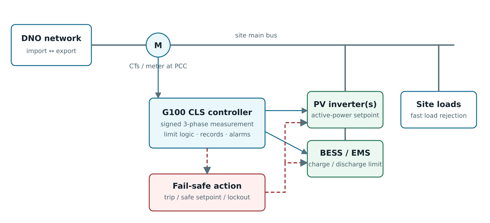
What a compliant CLS must do
- measure import/export in the correct direction at the agreed Connection Point, across all relevant phases;
- manage every relevant generator, storage system and controllable load needed to respect the limit;
- respond to rapid load rejection and other credible changes quickly enough to meet the standard and DNO agreement;
- enter a safe condition if measurement, control, communications, actuator or auxiliary-supply failures prevent assured limitation;
- control access to settings, prevent casual tampering and preserve the approved limit;
- provide alarms, event records and the required state/lockout behaviour;
- be type tested as a complete CLS arrangement where possible, or supported by accepted site-specific evidence;
- be installed, commissioned and documented using the agreed scheme and current forms.
The G100 logic distinguishes normal operation, corrective control after a limit excursion and a safe/locked condition when the scheme cannot reliably restore compliance. The official type-test templates test state transitions, repeated excursions, failures and reset/lockout. Exact timers, permitted excursions and reset rules must come from the current G100 document and approved product evidence—not an installer’s generic PLC narrative.
G100 is not these things
- It is not a substitute for G98 or G99. The generation/storage still needs the correct connection route.
- It is not simply a maximum kW value typed into one inverter if other devices can export.
- It is not an assumption that the site load will always absorb generation. Loads can trip.
- It is not the same as a flexible connection controlled dynamically by DNO ANM/DERMS. G100 normally enforces a local agreed boundary; a flexible connection responds to changing network constraints and a curtailment instruction.
- It is not “zero export” by marketing claim. A zero-export system still requires an agreed measurement, response and fail-safe design.
7. End-to-end implementation workflow
- Identify the network operator and jurisdiction. Use the site postcode/MPAN to confirm DNO or IDNO, voltage, phase arrangement and whether the project is in GB or Northern Ireland.
- Define the complete plant. List existing and new PV, wind, CHP, generators, UPS systems capable of parallel operation, BESS, V2G and controllable loads. Record intrinsic/basic design capacity, inverter rating, phase allocation and all operating modes.
- Establish the connection point and power convention. Mark the DNO–customer ownership boundary, PCC metering location, normal import/export direction and every path that could bypass measurement or tripping.
- Select G98 or G99. Check aggregate current/capacity, public LV connection, type-test status and multi-premises rules. Never select the route only from the requested export limit.
- Decide the capacity strategy. Compare unrestricted connection, network reinforcement, G100 fixed limitation and a DNO flexible connection. Include curtailment energy, availability, future expansion and lifecycle costs.
- Perform preliminary studies. At minimum consider load flow/voltage rise, fault level, protection, harmonics, flicker, unbalance, earthing and thermal capacity. Larger types need detailed models, dynamic studies and capability evidence.
- Submit the application before commitment. For G99, obtain an acceptable connection offer before connecting and ideally before non-cancellable equipment procurement. Use the current G99 SAF, supplementary forms and DNO portal. G100 needs its scheme information in addition to the generation application.
- Accept the offer and freeze requirements. Capture Maximum Export/Import Capacity, connection voltage, reinforcement, protection settings, communications, monitoring, witness tests, milestones and operational-notification conditions.
- Complete detailed design. Produce the approved single-line, protection philosophy, calculations, CT/VT design, earthing, G100 functional design specification, trip matrix, auxiliary supply and cybersecurity/access-control plan.
- Verify products and configuration. Match exact model and firmware to ENA type-test records. Confirm the CLS includes the actual meter, controller, communications and controlled device combination; product entries often contain restrictions.
- Factory and bench test. Simulate limits, direction, loss of load, meter/CT faults, communications failure, controller power loss, actuator failure, lockout and recovery before site energisation.
- Install and commission. Prove CT/VT polarity, phase rotation, signed power, all trip paths, protection settings, time synchronisation, fail-safe behaviour, alarms, labels, interlocks and setting security.
- Complete DNO witness and operational notification. Provide as-built drawings, settings, test sheets, compliance forms and PGMD/models where applicable. Do not begin permanent parallel operation before the required permission.
- Operate under change control. Firmware, inverter replacement, new EV chargers, altered site loads, CT ratio, controller software or connection topology can invalidate compliance. Maintain, periodically test and notify the DNO where required.
ENA’s Connect Direct service supports digital G98, G99 and G100 submissions across participating network operators. DNO-specific portals and forms also remain important; use the route named by the operator.
8. What a good G99/G100 application package contains
| Document/data | Content that prevents queries and redesign |
|---|---|
| Site and connection data | Address, MPAN, DNO/IDNO, existing connection agreement, supply voltage, agreed import/export capacities, earthing and ownership boundary. |
| Single-line diagram | Existing and new equipment, ratings, transformers, cables, breakers, isolators, CTs/VTs, PCC, revenue meter, G99 interface point, G100 measurement and fail-safe trip paths. |
| Plant schedule | Every generating/storage unit, manufacturer, exact model, firmware, AC rating, intrinsic/basic design capacity, registered capacity, phase allocation and ENA Product ID. |
| Operating philosophy | Import, export, battery charge/discharge, island mode, standby/parallel test, black start, load rejection, maintenance bypass and degraded modes. |
| Network studies | Maximum/minimum load flow, voltage, fault contribution, protection grading, harmonics to G5, flicker to P28, unbalance to P29 and dynamic studies where required. |
| Protection package | Relay make/model, diagrams, CT/VT details, proposed functions/settings, trip matrix, DC system, breaker data, LoM evidence and test method. |
| G100 functional design | Limit values and sign convention, meter location/class/CT ratio, control law, scan/response time, controlled devices, communications, fail-safe matrix, state/lockout/reset, alarms, logs and access control. |
| Compliance evidence | Type-test reports, product register references, PGMD, models, manufacturer declarations and any site-specific deviations. |
| Programme | Procurement, DNO works, protection/CLS FAT, energisation, witness testing, staged capacity and final documentation dates. |
9. Worked example: 500 kW PV + BESS with a 100 kW export limit
9.1 Project definition
A 400 V commercial site has a 120 kW typical daytime demand and a measured 35 kW minimum demand. It proposes:
- 250 kWp PV array with a 200 kW three-phase inverter;
- 300 kW / 600 kWh battery energy storage system;
- maximum combined export-capable AC plant of 500 kW;
- a DNO-agreed Maximum Export Capacity of 100 kW;
- a G100 CLS at the main 400 V connection point.
The project is G99 Type A because the registered/export-capable generating module is below 1 MW but far outside G98. The 100 kW boundary does not turn it into a 100 kW plant. G100 is added to enforce the connection limit.
9.2 Power-balance calculation
Define import as positive and battery discharge as positive:
Export occurs when Pgrid is negative, and the requirement is Pgrid ≥ −100 kW.
| Scenario | Load | PV | BESS | Uncontrolled grid flow | CLS action |
|---|---|---|---|---|---|
| Normal sunny operation | 120 kW | 180 kW | 0 | −60 kW (60 kW export) | No curtailment; within 100 kW limit. |
| Minimum load, full PV | 35 kW | 200 kW | 0 | −165 kW | Curtail at least 65 kW, or charge BESS by at least 65 kW. |
| Minimum load, PV + requested discharge | 35 kW | 200 kW | 300 kW discharge | −465 kW | Block/curtail a total of at least 365 kW across BESS and PV. |
| PV plus fast load rejection | Falls 120 → 10 kW | 200 kW | 0 | changes −80 → −190 kW | Reduce generation/absorb power fast enough; fail-safe if closed-loop control cannot comply. |
| High import during charging | 180 kW | 20 kW | −300 kW (charge) | +460 kW import | If an import limit applies, reduce battery charge and/or flexible loads. |
9.3 Control design
A practical hierarchy is:
- the PCC meter produces a signed three-phase active-power measurement;
- the CLS compares measured flow with an internal control target that includes a design margin below the contractual 100 kW boundary;
- first, the battery absorbs surplus if state of charge, temperature and availability permit;
- second, the CLS curtails PV and blocks BESS discharge;
- if compliance cannot be assured, a hardwired safe action disconnects or forces relevant devices to a verified non-exporting condition;
- events, excursions, failed commands and resets are timestamped and retained.
The margin is an engineering value derived from meter accuracy, CT error, communications delay, inverter ramp response, site-load variability and the DNO-agreed limit. It must not be an arbitrary “5%.” The controller must also handle battery state-of-charge saturation: a full battery cannot absorb PV surplus.
9.4 Failure-mode and effects analysis
| Failure | Detection | Required design response | Commissioning proof |
|---|---|---|---|
| Loss of controller auxiliary supply | Power-fail relay/watchdog | Relevant generation/storage moves to the approved safe state; alarm retained where possible. | Isolate each auxiliary source and time the full response. |
| PCC meter/CT signal frozen, implausible or lost | Quality flag, heartbeat, range/rate validation | Do not continue unlimited operation using the last “good” low-export value. | Open signal, freeze data, inject bad quality and reverse polarity. |
| Communications loss to PV | Command acknowledgement/heartbeat | Trip or force PV to a safe limit through an independent path. | Disconnect network cable/fibre and prove final power at PCC. |
| BESS ignores setpoint | Compare command with measured response | Escalate to hardwired block/trip and curtail other devices. | Simulate actuator failure during export. |
| Site load trips | PCC power step | Fast corrective control without assuming load recovery. | Open a representative load bank or use a signal-injection test agreed with the DNO. |
| Operator changes limit | Role-based access and audit log | Prevent unauthorised settings above the connection agreement. | Attempt local/remote unauthorised changes; verify seals/password roles. |
| Repeated limit excursions | State/event counters | Enter the G100-required locked safe state and apply the approved reset policy. | Repeat controlled excursions and verify non-volatile records/lockout. |
9.5 Site acceptance tests
- Prove CT ratio, polarity, phase association and import/export sign against an independent reference meter.
- Test minimum, intermediate and maximum configured limits as required by the approved evidence.
- Operate at normal flow, approach the limit and step beyond it.
- Simulate the maximum credible rapid load loss.
- Prove command and hardwired fail-safe paths to every relevant device.
- Fail each communications link and auxiliary supply independently.
- Verify state transitions, excursion count, lockout, non-volatile storage and authorised reset.
- Confirm alarms reach the responsible operator and have actionable text.
- Record response at the PCC—not only controller setpoints—with synchronised test equipment.
- Return all temporary links, test modes and overrides to the documented as-left state.
The response interval is a controlled design parameter, not a generic inverter setting. National Grid Electricity Distribution’s current customer-limitation guidance, for example, says its CLS should typically restore import/export within 15 seconds, with a maximum reaction time of 60 seconds, including for fail-safe action. Earlier export-only summaries and other project arrangements may show different figures. Use the current G100 text, accepted type-test evidence and your signed connection offer; do not assume that one web summary is the complete test specification.
10. Commissioning, witness testing and operational notifications
Commissioning intensity increases from a type-tested Type A installation to Type B–D plant. Typical activities include:
- visual inspection against approved drawings and equipment schedules;
- primary/secondary injection of interface protection and end-to-end trip timing;
- breaker opening, trip-circuit supervision and fail-safe tests;
- functional tests of voltage, frequency, LoM, reconnection and active/reactive-power controls;
- power-quality and fault-recording/monitoring commissioning where specified;
- G100 operating-state, response-time, communications-failure and lockout tests;
- submission of installation forms, PGMD, models, type-test evidence and as-built records.
Type A uses the applicable installation documentation as the final compliance record. Type B–D projects typically progress through more formal operational notifications, and a Final Operational Notification (FON) is issued after the DNO accepts the required evidence. The DNO may witness tests. One current DNO guide, UK Power Networks’ witness-testing guidance, explains that commissioning programmes, forms and evidence depend on module type. The accepted connection offer and current G99 forms are authoritative for the project.
11. Other requirements that may apply
| Requirement | When it becomes relevant | Relationship to G98/G99/G100 |
|---|---|---|
| BS EN 50549-1 / -2 | Generator interface requirements for LV and MV distribution connections. | Technical product/interface standards referenced by the GB connection framework; they do not replace the EREC process. |
| EREC G5 Issue 5 | Harmonic sources, converter-rich plant, resonances and aggregate distortion. | Power-quality study alongside G99; type testing alone may not prove site-level compliance. |
| EREC P28 Issue 2 | Voltage fluctuations, rapid voltage change and flicker from switching or variable output. | Connection planning study; the 2025 EREP 28 is an application guide. |
| EREC P29 | Single-phase concentration or equipment causing voltage unbalance at 132 kV and below. | Important for phase allocation and multi-unit schemes; listed by ENA as current under revision. |
| EREC G74 / IEC 60909 methods | Fault-current calculation and assessment. | Supports G99 fault-level and protection studies. |
| EREC G12 | Protective multiple earthing, especially LV generation/storage/EV arrangements. | Earthing safety remains separate from export control. |
| BS 7671 | Electrical installations, wiring, protection, isolation, earthing and verification. | Mandatory installation-design context; DNO approval does not certify BS 7671 compliance. |
| ESQCR | Safety, quality and continuity obligations for public electricity networks and connected parties. | Part of the legal context behind notification, safe parallel operation and voltage/frequency quality. |
| Distribution Code / connection agreement | Every DNO-connected project. | Makes project-specific obligations, limits and operating arrangements enforceable. |
| Grid Code / NESO requirements | Transmission connections and certain significant embedded generation interactions. | Additional to, not replaced by, G99. |
| ENA type-test register and cybersecurity requirements | Type-tested inverters, interface protection and CLS products; remote-control functions. | Evidence and lifecycle controls must match the exact installed hardware/software. |
12. Common mistakes—and the engineering correction
| Mistake | Why it fails | Correct approach |
|---|---|---|
| Classifying a plant by the export cap | A 500 kW installation limited to 100 kW is not automatically a 100 kW generator. | Classify installed/registered capacity under G99, then add G100 for the boundary. |
| Adding individual inverter ratings but ignoring existing plant | The network sees the aggregate installation and credible operating modes. | Create a complete existing-and-proposed plant schedule first. |
| Calling an inverter setting “G100” | It may not measure the PCC, control all devices or fail safely. | Verify the complete type-tested CLS combination and site architecture. |
| Relying on permanent site load | Loads trip, stop or move to another bus. | Design and test the worst credible load rejection. |
| Using CTs with wrong polarity/phase | The controller may increase export when it intends to reduce it. | Primary prove signed power on every phase and under import/export. |
| Assuming communications failure is harmless | Last-command hold can leave generation unrestricted. | Define detected failure, timeout and independent safe action. |
| Copying protection settings from another site | Connection voltage, DNO schedule, VT arrangement and system studies differ. | Use the approved project schedule and test it end to end. |
| Equating MCS with DNO approval | MCS addresses product/installer quality; it is not the grid connection permission. | Complete both applicable schemes and retain both records. |
| Buying plant before the DNO offer | Reinforcement, fault-level or protection requirements can change the design. | Apply early and place procurement under appropriate technical conditions. |
| Ignoring later firmware or plant changes | Type-test validity, response and fail-safe behaviour can change. | Operate a controlled modification and DNO notification process. |
13. Frequently asked questions
Is G99 a law?
It is an Engineering Recommendation, not an Act of Parliament. In practice its requirements are incorporated through the GB distribution framework, DNO connection process and connection agreement, within a legal environment that includes ESQCR. A customer cannot treat it as optional merely because its title says “Recommendation.”
Does a battery always need G99?
A battery that can export or operate in parallel is treated as generating equipment for the relevant mode. A small, fully type-tested installation may qualify for G98; combinations with existing generation commonly move into G99 or a small-generation fast-track process. A non-exporting charger is a load, but its import may still affect the connection and could use G100 import limitation.
Can G100 avoid all reinforcement?
No. The DNO may still require reinforcement for fault level, voltage, protection, security, thermal duty during the CLS response interval, import capacity or other network constraints. G100 is an option the DNO may accept, not a right to connect unlimited equipment.
Can I use any PLC for G100?
A site-specific engineered system may be possible if the DNO accepts the compliance evidence, but a general-purpose PLC program is not automatically compliant. Fully type-tested registered schemes are normally easier to assess. The whole chain—measurement, controller, communications, device response, fail-safe, states and lockout—must meet the current requirements.
What is the difference between G100 and a flexible connection?
G100 locally holds flow within a pre-agreed customer boundary. A flexible connection normally accepts a larger connection subject to dynamic curtailment commanded by the DNO’s active network management/DERMS according to real-time network constraints. A project could have both local limitation and a flexible service, but the control hierarchy and fail-safe responsibilities must be explicit.
What if a generator parallels for only a few seconds?
Intentional closed-transition transfer or parallel testing is still parallel operation. G99 provides a route for infrequent short-term parallel operation, but the DNO must agree the design, duration, protection and interlocking. A true break-before-make standby supply is a different case.
Who is responsible?
The generator/customer retains the connection obligation. The EPC/installer designs and documents the installation; manufacturers provide valid product evidence; the protection/control engineer produces settings and proves the scheme; and the DNO assesses and authorises the connection. Contracting out the design does not remove the owner’s operational and change-control responsibilities.
14. Final project checklist
Before application
- DNO/IDNO, jurisdiction, MPAN, voltage, phases and connection point confirmed.
- Existing and proposed generation/storage/V2G/UPS plant fully inventoried.
- G98/G99 route and G99 Type confirmed using registered—not limited-export—capacity.
- Unrestricted, reinforcement, G100 and flexible options compared commercially and technically.
- Correct current forms and exact type-test references identified.
Before detailed procurement
- Connection offer accepted and capacities, settings, studies, works and witness requirements captured.
- Single-line, operating philosophy, protection and CLS functional design approved.
- Model/firmware/product combinations match valid ENA evidence.
- Fault level, voltage, thermal, G5, P28 and P29 requirements closed.
- G100 FMEA covers power, meter, CT, communications, actuator, load rejection and unauthorised change.
Before permanent parallel operation
- As-built drawings and controlled settings match the installed plant.
- Protection and CLS have passed end-to-end, response and fail-safe tests at the PCC.
- DNO witness tests and remedial actions are complete.
- Required installation documents, PGMD, models, results and certificates are submitted.
- The required operational notification/permission has been received.
- Owner has maintenance, alarm-response, access-control and modification procedures.
15. Authoritative sources and further reading
- Energy Networks Association, EREC G98 Issue 2 catalogue entry, April 2026.
- Energy Networks Association, EREC G99 Issue 2: scope, status and revisions, March 2025.
- Energy Networks Association, EREC G100 Issue 2 Overview and Summary Guide, and G100 Issue 2 Amendment 2 publication, April 2023.
- Energy Networks Association, All G98 and G99 forms.
- Energy Networks Association, Connect Direct.
- National Grid Electricity Distribution, Microgeneration single-premises G98 guidance.
- National Grid Electricity Distribution, G99 fast-track and Small Generation Installation routes. Eligibility is route- and DNO-specific; verify current criteria.
- National Grid Electricity Distribution, Customer Export/Import Limitation Schemes.
- UK Power Networks, Distributed energy resources connection guidance.
- UK Power Networks, Flexible connections.
- Energy Networks Association, Type Test Verification Report Register for generation and limitation products.
- Energy Networks Association, Document Catalogue for G5, P28, P29, G12, G74 and the latest revisions.