

The RTXP 24 is a deceptively simple device. From the front it looks like two narrow hinged doors beside a protection IED. Electrically, however, it is the controlled boundary between live instrument-transformer and breaker-control circuits on one side and the relay under test on the other. Its job is not merely to provide convenient test sockets. Its contact geometry forces critical circuits to change state in a safety-oriented sequence.
That sequence is the reason RTXP exists: trip circuits are interrupted before the measurement circuits are transferred; CT secondaries are short-circuited automatically before the relay current path is opened; VT and other circuits are isolated without being shorted; and a dedicated contact can place the IED in test mode. When the handle is removed, the sequence is reversed and the trip path is restored last.
This guide combines current Hitachi Energy documentation with a physical inspection of a new Hitachi-branded RTXP 24, order code RK 926 315-AK. It explains what the printed symbols mean, how to use the switch in a secondary-injection test, what must be verified before relying on the automatic sequence, and which claims cannot be made from the product suffix alone.
Safety boundary
RTXP 24 is used in CT, VT, DC auxiliary and circuit-breaker trip circuits. An open-circuited energized CT secondary can generate dangerous voltage; an incorrect test connection can backfeed a VT circuit or operate a breaker. Work must be performed by authorized protection personnel under the approved switching, isolation, test and restoration procedure. This article does not replace the project drawings, the IED manual, the test-set manual or the applicable site safety rules.
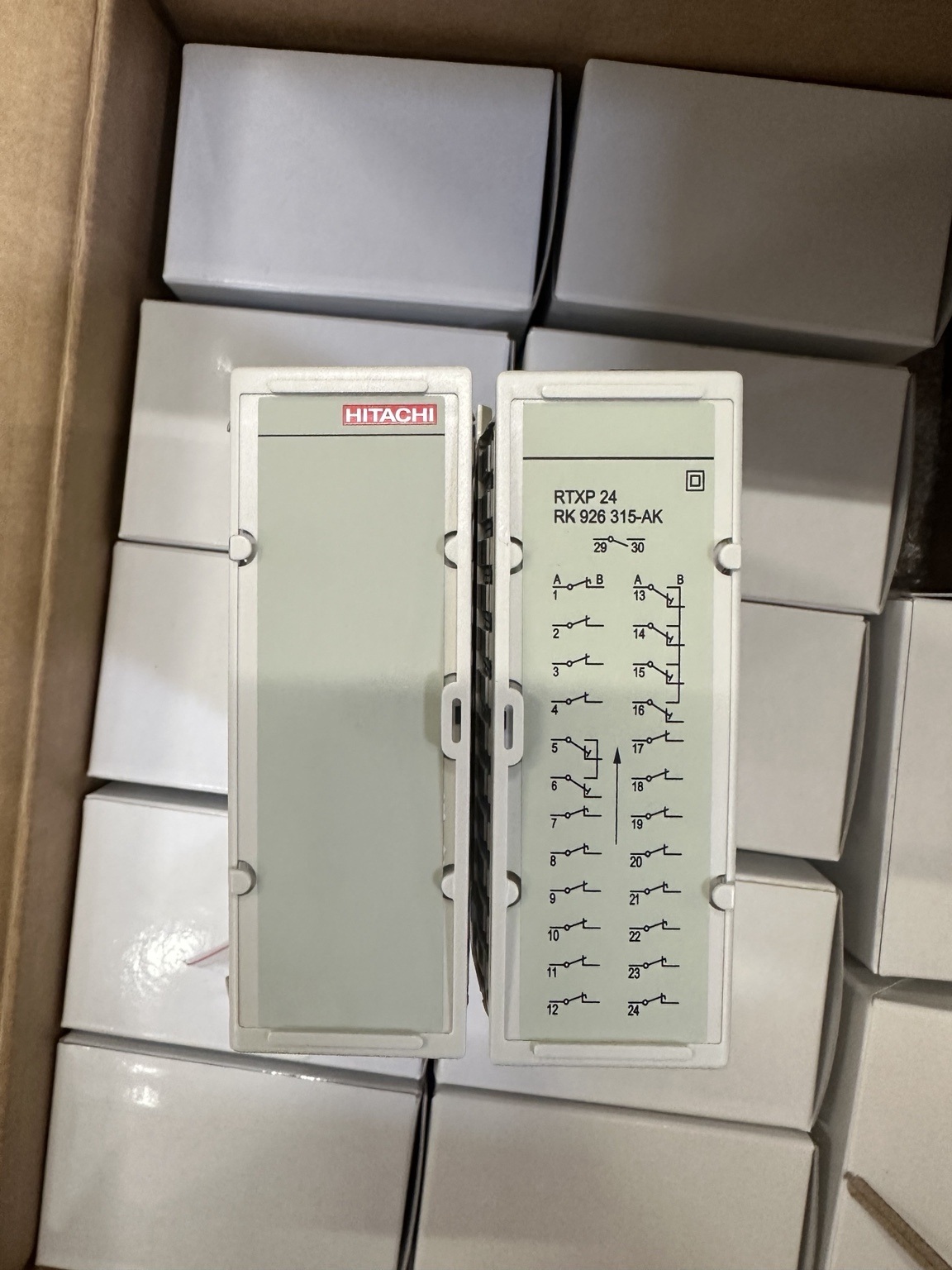
RTXP 24 at a glance
| Item | Engineering meaning |
|---|---|
| Manufacturer terminology | COMBITEST test switch; “test block” is common field terminology |
| Photographed variant | RTXP 24, RK 926 315-AK |
| Construction | Two housings assembled as one unit, up to 12 contact units per housing |
| COMBIFLEX space | 3U × 12C front space |
| Main test accessory | RTXH 24-1 test-plug handle, order code 1MYN000029-CC in the current buyer’s guide |
| Dedicated indication | Normally-open 29–30 “In test mode” contact |
| Main safety functions | Early isolation of trip circuits, automatic CT shorting, VT/general-circuit isolation and controlled restoration |
| Test-contact rating stated by Hitachi Energy | 20 A continuous; 500 A for 1 s |
| Signalling-contact rating stated by Hitachi Energy | 10 A continuous; 150 A for 1 s |
| Highest system voltage stated for the test system | 600 V DC or 500 V AC |
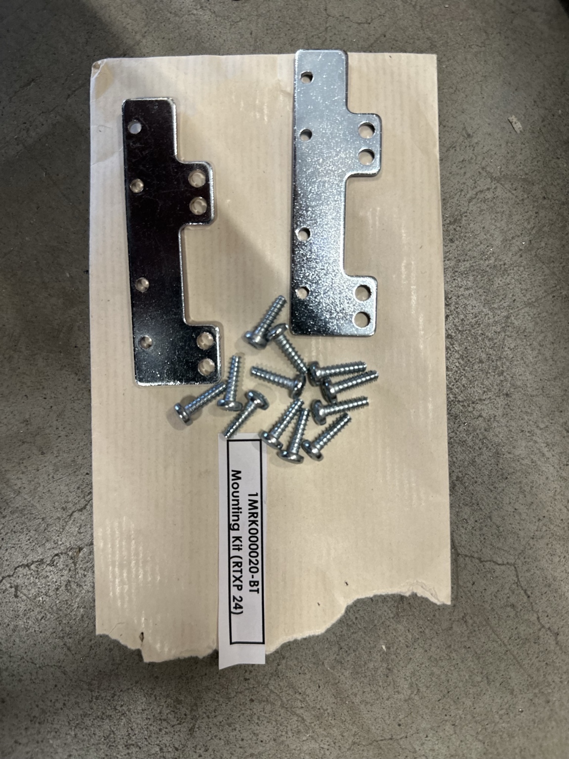
| Mounting accessory visible in the photographs | 1MRK 000 020-BT, identified by the manufacturer as the RTXP 24 mounting kit for a 4U rack assembly |
The values above are component/test-system data, not permission to apply those limits blindly to an installed relay panel. The permissible duty of the complete path is the lowest rating among the RTXP contact, COMBIFLEX socket and conductor, IED terminal/input, auxiliary component and project wiring. Some IED documentation states a lower short-time current for the complete arrangement.
Why a purpose-built test switch is needed
Secondary injection is easy only when the relay is already isolated on a workbench. In an energized substation panel, four different problems must be solved at the same interface:
- The breaker must not trip unintentionally. Transients created while transferring analog or auxiliary circuits must not reach an in-service trip coil.
- An energized CT secondary must never be left open. The CT must see a continuous low-impedance secondary path while the relay input is disconnected.
- A VT secondary must not be short-circuited or backfed. The relay side must be isolated from the live VT before a test voltage is applied.
- The IED and station system must know that testing is in progress. Test mode should suppress or qualify selected outputs, events and communications according to the approved logic—not according to assumption.
Hitachi Energy describes COMBITEST as an interface between the primary-equipment circuits and the protection relay. Inserting the correct test handle isolates the relay and exposes the relay side for test injection. The manufacturer explicitly states that CT shorting is automatic and that no external CT shorting links are required on the test handle. It also states that the trip circuits are interrupted before CT shorting during handle insertion.
That mechanical sequencing is valuable, but it does not eliminate engineering verification. A correctly manufactured RTXP cannot compensate for a wrongly assigned terminal, a missing shorting bar, a miswired CT neutral, an incorrect TESTMODE input or a project drawing that does not match the installed switch.
What is inside an RTXP 24?
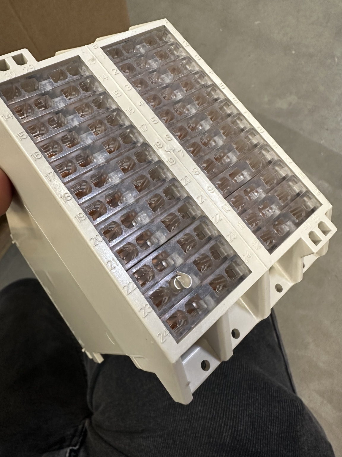
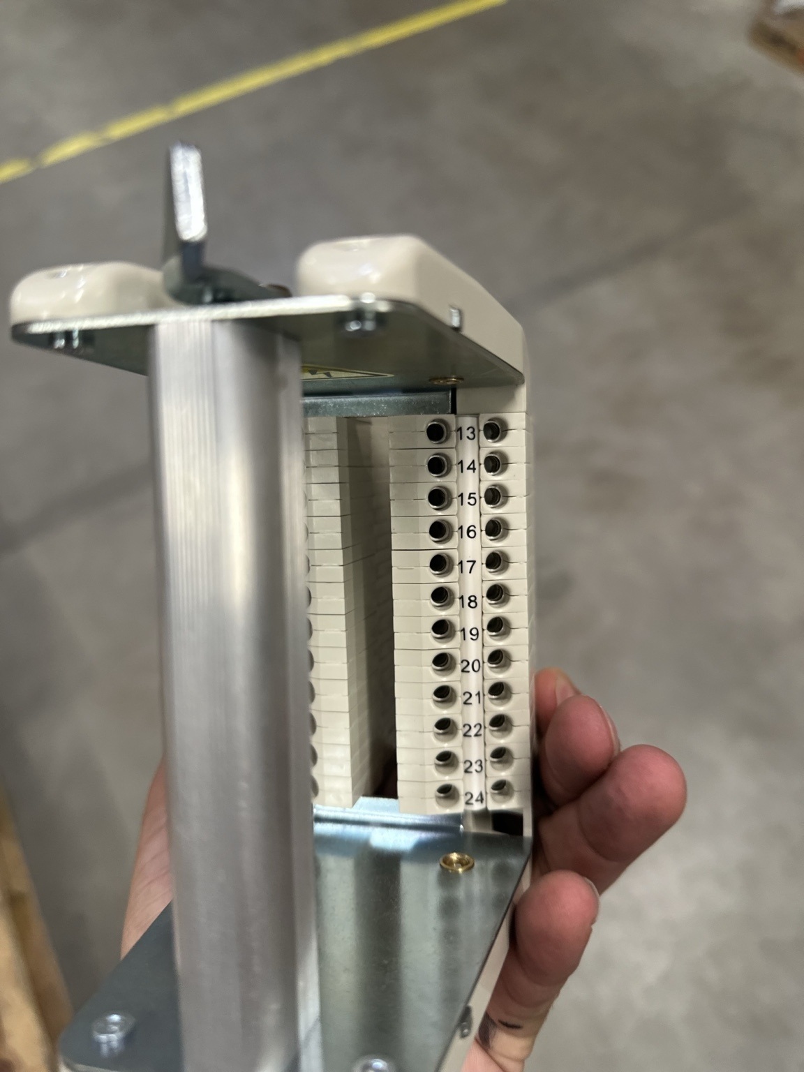
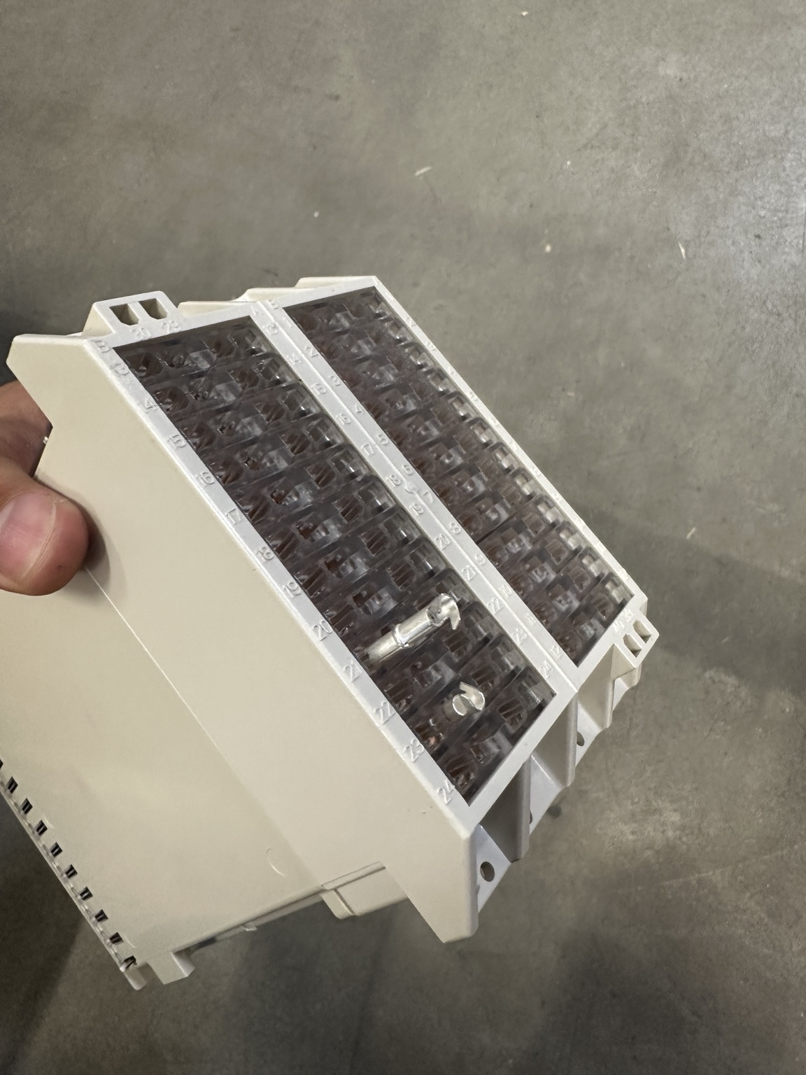
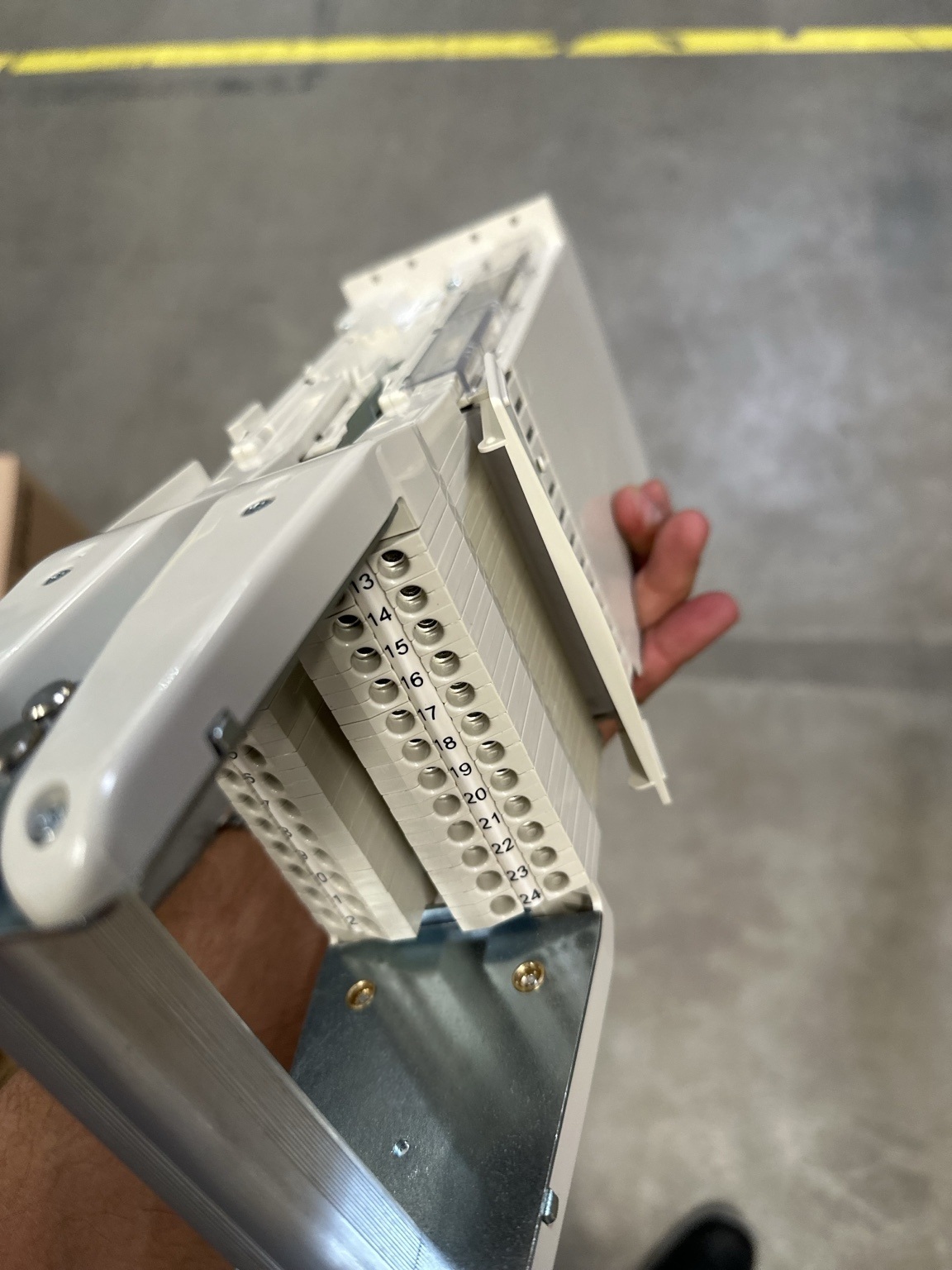
The RTXP 24 contains two side-by-side housings. Each position can carry a contact unit selected for a particular circuit duty. At the rear, the positions are numbered 1–12 in one housing and 13–24 in the other. Each position is represented on the face diagram by two sides, A and B.
The A/B letters identify the two sides of the contact unit; they are not a universal promise that A is always “IED” and B is always “field,” or vice versa. Use the approved project terminal diagram to establish the actual circuit direction. On the RK 926 315-AK face symbol, the internal current-group shorting links are drawn on the B side, but the external allocation still has to be verified from the scheme.
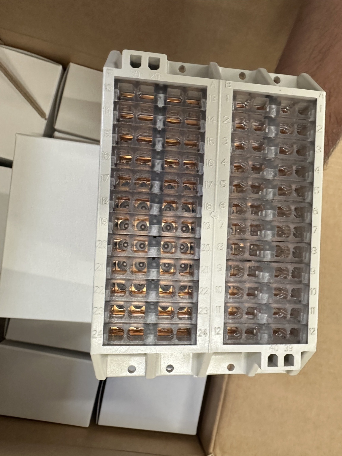
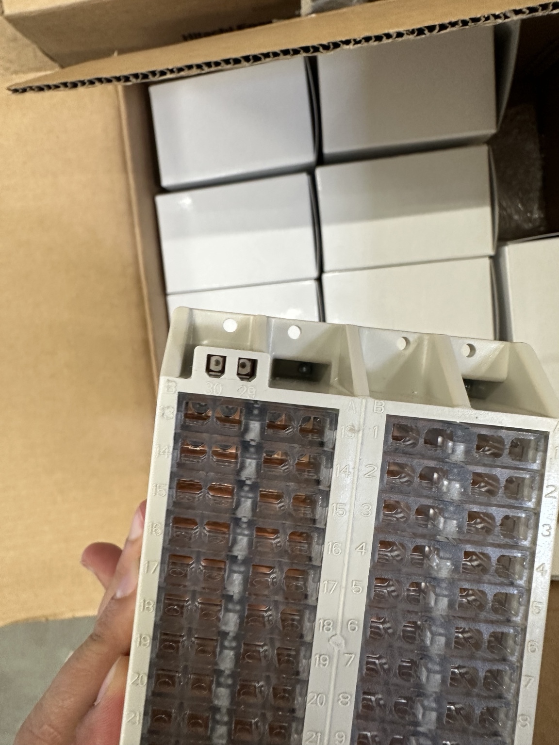
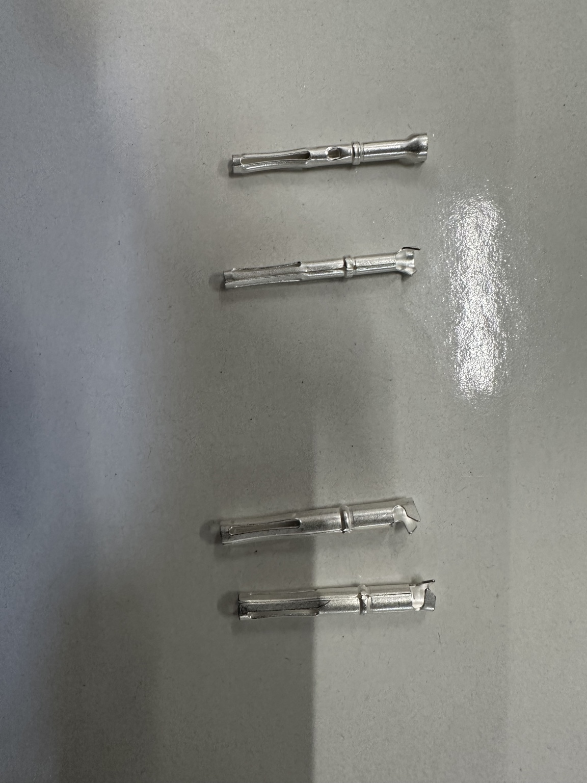
The rear connection points accept COMBIFLEX sockets crimped to the panel wiring. Hitachi Energy specifies 20 A COMBIFLEX sockets for CT and VT circuits in applicable 650/670-series installations. Socket type, conductor size, crimp tooling and pull-test requirements must follow the applicable connection-components documentation and the project workmanship specification.
The three functional contact classes
1. Trip contact: early break, late make
A trip-type contact opens first while the test handle is being inserted and closes last while the handle is being removed. This timing removes the breaker trip path before analog circuits are disturbed and keeps it isolated until the relay and measurement circuits have returned to a stable normal condition.
This is not the same as saying every relay output is automatically safe. Only circuits actually routed through correctly selected trip-type positions are isolated. Trip Coil 1, Trip Coil 2, breaker-failure initiate, transfer trip, lockout and other high-consequence outputs must each be traced on the project drawings.
2. Current contact: make-before-break CT shorting
Current positions include an internal shorting arrangement. During insertion, the transformer-side current group is shorted before the through-contact to the relay opens. During withdrawal, the relay path is re-established before the temporary short is removed. This is the essential make-before-break behavior for CT safety.
The shorting group must include the correct phase and return/neutral conductors for that specific CT circuit. Never infer the grouping from adjacent numbers alone; read the vertical shorting-bar symbol printed on the installed variant and compare it with the approved schematic.
3. Voltage/general contact: disconnect without shorting
The other standard contact type is used for VT inputs, auxiliary power, binary signals and other circuits that require isolation but no automatic short. Its transition is coordinated with the handle movement, but it must not be mistaken for a CT contact. Using a general contact where CT shorting is required defeats the primary safety function of the test switch.
Decoding the photographed RK 926 315-AK arrangement
The exact switch in the photographs is marked RK 926 315-AK. Its face label and Hitachi Energy symbol catalogue 1MRK001024-CA show the following contact classes.
| Position(s) | Symbol shown on the -AK label | Functional interpretation | What must be confirmed in the project drawing |
|---|---|---|---|
| 1 | Trip-type contact | Early break on insertion; late make on withdrawal | Which trip/output circuit is routed here |
| 2–4 | Standard disconnect contacts | Suitable for assigned voltage, auxiliary or signal circuits | Actual circuit, polarity and source |
| 5–6 | Two-position current shorting group | B-side positions are shown as one shorting group | CT core/function and return arrangement |
| 7–12 | Standard disconnect contacts | Assigned according to the project scheme | VT, DC, binary or spare status |
| 13–16 | Four-position current shorting group | B-side positions are shown as one shorting group | Phase and neutral/return allocation and CT polarity |
| 17–24 | Standard disconnect contacts | Assigned according to the project scheme | VT, DC, binary, outputs or spare status |
| 29–30 | Normally-open signalling contact | “In test mode” indication when actuated by the test handle | IED binary-input voltage, logic, event and output behavior |
Important distinction
The suffix -AK identifies a manufactured contact arrangement, not the final project wiring. Hitachi Energy product guides commonly associate RK 926 315-AK with single-breaker, single- or three-phase-trip applications and internal neutral on the current circuits. Other current product documentation uses additional application descriptors. The safe rule is therefore: select by the manufacturer’s configuration table, but commission by the face symbol and the approved terminal diagram.
What “internal neutral” means here
In this context, “internal neutral” refers to the way a current-input group is arranged and shorted within the test-switch configuration. It must not be confused with:
- the power-system neutral;
- the single permitted secondary earth of a CT circuit;
- an IED’s numerical residual-current calculation; or
- a separate core-balance CT input.
The CT secondary earthing point must remain controlled and unique according to the protection design. The RTXP shorting function is temporary test isolation; it is not a substitute for the permanent CT earthing philosophy.
Contact 29–30 and IED TESTMODE
The separate 29–30 contact is normally open. Hitachi Energy’s 650/670-series guidance states that it should be wired to the input of the IED test function block so that inserting the RTXP test handle activates test mode.
This interface deserves its own commissioning test:
- Confirm 29–30 is open with the RTXP in normal service condition.
- Insert the correct RTXH 24 test handle under the approved procedure.
- Confirm 29–30 closes and the assigned IED binary input changes state.
- Confirm the IED’s global TESTMODE indication and the intended function-test modes.
- Verify which outputs, reports, GOOSE messages, LEDs, alarms and disturbance records remain active, blocked or test-qualified.
- Remove the handle and confirm the input and every temporary test function return to normal.
Do not assume “IED in test mode” automatically blocks all physical trip contacts. Test mode is configuration-dependent, and physical output isolation remains essential. Conversely, do not assume an open trip circuit alone puts the IED or SCADA system into test mode.
The current COMBITEST buyer’s guide also notes a subtle but important behavior: inserting the RTXF block-plug handle does not activate the RTXP 24 test-mode signalling contact. That difference matters if procedures use an RTXF for isolation but rely on 29–30 to suppress station indications.
The safe operating sequence
Inserting the RTXH 24 test handle
The intended sequence can be understood as four safety layers:
| Stage | Mechanical/electrical action | Purpose |
|---|---|---|
| 1 | Test indication is initiated through 29–30 when the test handle actuates it | Allows the IED/test logic to recognize the test condition |
| 2 | Trip-type contacts open | Prevents relay/test transients from operating the breaker |
| 3 | CT-side current groups are short-circuited | Preserves a safe CT secondary path |
| 4 | Current, voltage and assigned general contacts disconnect from the in-service circuit; relay-side test access becomes available | Permits controlled secondary injection into the isolated IED |
The exact overlap and travel are created by the contact geometry. The operator should not try to reproduce the sequence using random plugs or loose jumpers.
Removing the handle
The restoration process is the safety-critical reverse transition:
- Test-set outputs are reduced to zero and the test set is stopped.
- Test leads are removed or placed in the documented safe state.
- Relay measuring inputs and ordinary circuits reconnect.
- CT shorting is released only after the normal current path is re-established.
- The relay is allowed to reset and stabilize.
- Trip circuits restore last when the handle is completely withdrawn and its latches are released.
- TESTMODE, forced signals, blocked functions and station indications are verified normal.
Hitachi Energy’s commissioning guidance stresses that trip and alarm circuits are not restored until the test handle is completely removed. A partly withdrawn or latched handle must therefore be treated as a defined intermediate test state—not as normal service.
RTXP, RTXH, RTXF, RTXB and RTXM: do not mix them up
| Part | Function | Critical limitation |
|---|---|---|
| RTXP 24 | Fixed test switch installed in the protection/control panel | Contact arrangement varies by complete order suffix |
| RTXH 24-1 | Full test-plug handle providing test access and sequenced transfer | Use the matching handle and verified lead assignment |
| RTXF 24 | Block-plug handle disconnecting circuits routed through the switch | Manufacturer states it does not actuate the RTXP 24 test-mode contact |
| RTXB | Short red trip-block plug that opens a trip-type contact | It is position-specific isolation, not full relay isolation |
| RTXM | Ammeter test plug with local automatic shorting protection | Intended for current measurement; do not substitute ordinary probes |
The current buyer’s guide lists:
- RTXH 24-1 test-plug handle: 1MYN000029-CC
- RTXF 24 block-plug handle: RK 926 016-AB
- RTXB trip-block plug: RK 926 005-AC
- RTXM ammeter test plug: RK 926 006-AB
- RTXP 24 mounting kit for 4U rack assembly: 1MRK 000 020-BT
Always recheck the latest regional ordering documentation before procurement. Similar-looking RTXP 8, RTXP 18, RTXP 24 and new-generation RTXP 12 accessories are not interchangeable merely because their plugs look related.
Practical secondary-injection workflow
The following method is intentionally equipment-neutral. It can be applied with an OMICRON, Megger, ISA, Doble or comparable calibrated relay test set, provided the approved test plan and manufacturer instructions are followed.
Phase A — Establish the test boundary
Before touching the RTXP:
- identify the exact protected bay, breaker, trip coils and remote-end consequences;
- obtain the approved single-line diagram, terminal diagram, DC schematic, trip matrix, IED configuration and settings revision;
- identify all CT cores and VT supplies routed through the switch;
- identify teleprotection, intertrip, breaker-failure initiate, autoreclose, lockout, process-bus and GOOSE consequences;
- decide whether the test stops at an isolated relay output, proves panel wiring to a test terminal, or intentionally operates a breaker;
- record the normal currents, voltages, binary inputs, output contacts and alarms before isolation;
- verify the test set is de-energized and all current/voltage outputs are at zero.
A secondary-injection test does not automatically authorize an operational breaker trip. If the test objective includes the trip coil and mechanism, that is a separately controlled functional test with its own switching program and safety boundary.
Phase B — Prove the installed RTXP configuration
- Read the complete order code from the face: RTXP 24 / RK 926 315-AK in this example.
- Compare every printed symbol with the project terminal diagram.
- Confirm that all CT circuits use current-type contact positions with the intended shorting group.
- Confirm every required trip path passes through a trip-type contact.
- Confirm the 29–30 circuit and IED TESTMODE assignment.
- Inspect the switch and handle for cracked housings, contamination, bent guide parts, overheated contacts, loose sockets or damaged latches.
- Verify the correct RTXH 24 handle and lead schedule; never rely on wire colour alone.
Phase C — Insert and verify before injecting
Insert the handle smoothly and in the intended orientation. Do not force it. Stop if the guides, doors or latches do not move normally.
Before connecting active test outputs, obtain positive evidence that:
- the IED reports test mode where intended;
- the selected physical trip paths are open;
- CT-side shorting is established for every applicable group;
- live VT and auxiliary sources are isolated from the relay-side injection points;
- no unexpected protection, breaker-failure, intertrip or SCADA event has been initiated;
- the test-set current return and voltage neutral connections match the approved lead schedule.
The acceptance method should be defined in the test procedure. Depending on the outage and circuit design, evidence may come from schematic-controlled continuity checks, measured states, IED metering, supervised current transfer or another approved method. Never place an ohmmeter onto a live CT, VT or DC circuit.
Phase D — Connect and test in layers
Start with the least energetic proof:
- Channel identity: inject a small value into one channel at a time and confirm the correct IED phase/input responds.
- Polarity and phase rotation: verify angles and sign convention before applying multi-phase quantities.
- Scaling: compare injected primary/secondary values with IED metering and configured CT/VT ratios.
- Protection elements: test pickup, dropout, timing, directional behavior, restraint and blocking as applicable.
- Logic: prove starts, trips, latches, LEDs, binary outputs and internal logic using the approved cause-and-effect matrix.
- External indications: verify event records, disturbance records, SCADA and IEC 61850 signals in the intended test-qualified state.
- Trip output: monitor the isolated output at the defined boundary. Energize an actual coil only when the switching program explicitly requires it.
For current injection, connect the test-set source and return before enabling the current output. For voltage injection, prove there is no VT backfeed path and keep test voltage within both the relay-input rating and the test-plan value. DC binary inputs require the correct station voltage, polarity and wetting arrangement.
Phase E — Controlled restoration
- Stop every active test state and set all analog outputs to zero.
- Remove test leads in the test-set manufacturer’s safe sequence.
- Reset operated protection functions, latches and output contacts.
- Clear forced binary inputs/outputs and temporary setting changes.
- Withdraw the handle smoothly; respect any latch/stabilization stage.
- Confirm normal CT and VT measurements return without phase or magnitude error.
- Confirm 29–30 opens and the IED leaves TESTMODE.
- Confirm trip-circuit supervision, breaker-failure, autoreclose, intertrip, alarm and SCADA functions are normal.
- Check that no RTXB, RTXM, temporary link, test lead or blocked function remains.
- Record independent restoration verification and release the bay under the site procedure.
Three common test applications
Overcurrent and earth-fault protection
Use single-phase injection first to prove the mapping of IL1, IL2, IL3 and residual/neutral inputs. Then test pickup and operating time at the required multiples. If residual current is calculated numerically, distinguish that from a separately wired neutral or core-balance CT input. The physical shorting groups on the -AK switch do not tell you which IED channel is assigned to each position; the terminal diagram does.
Directional, distance and differential protection
These functions require synchronized current and voltage channels, correct phase rotation and a verified reference direction. A safe RTXP transition does not prove CT/VT polarity or zone assignment. Perform a low-level phasor check before testing operate characteristics. For differential schemes, confirm which CT group is isolated and whether any remote or second-winding current remains connected.
Trip-output and breaker-circuit testing
With the trip circuit physically isolated, the relay output can be checked at the relay-side test boundary without operating the breaker. If the test requires a complete trip—including wiring, trip relay, coil, mechanism, auxiliary contacts and breaker-failure logic—restore or bypass only the specifically approved boundary and treat the action as an intentional breaker operation.
What an RTXP-based secondary-injection test proves—and what it does not
| It can prove | It does not prove by itself |
|---|---|
| Relay analog-channel response from the RTXP relay-side boundary | Primary CT ratio and polarity through the complete primary circuit |
| Protection pickup, timing and logic with simulated quantities | CT saturation performance under a real fault |
| Assigned binary inputs and isolated relay outputs | Mechanical breaker travel or interruption performance |
| TESTMODE behavior and selected station indications | Correct operation of every upstream/downstream circuit not included in the test boundary |
| Repeatable access without disturbing permanent wiring | That the installed wiring matches the drawing unless independently checked |
Combine secondary injection with CT ratio/polarity and loop tests, primary injection where required, end-to-end testing for communication schemes, and an intentional trip test when the project acceptance scope demands the full sensor-to-breaker chain.
Mechanical mounting and enclosure details
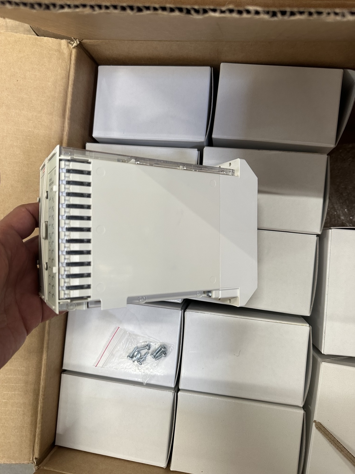
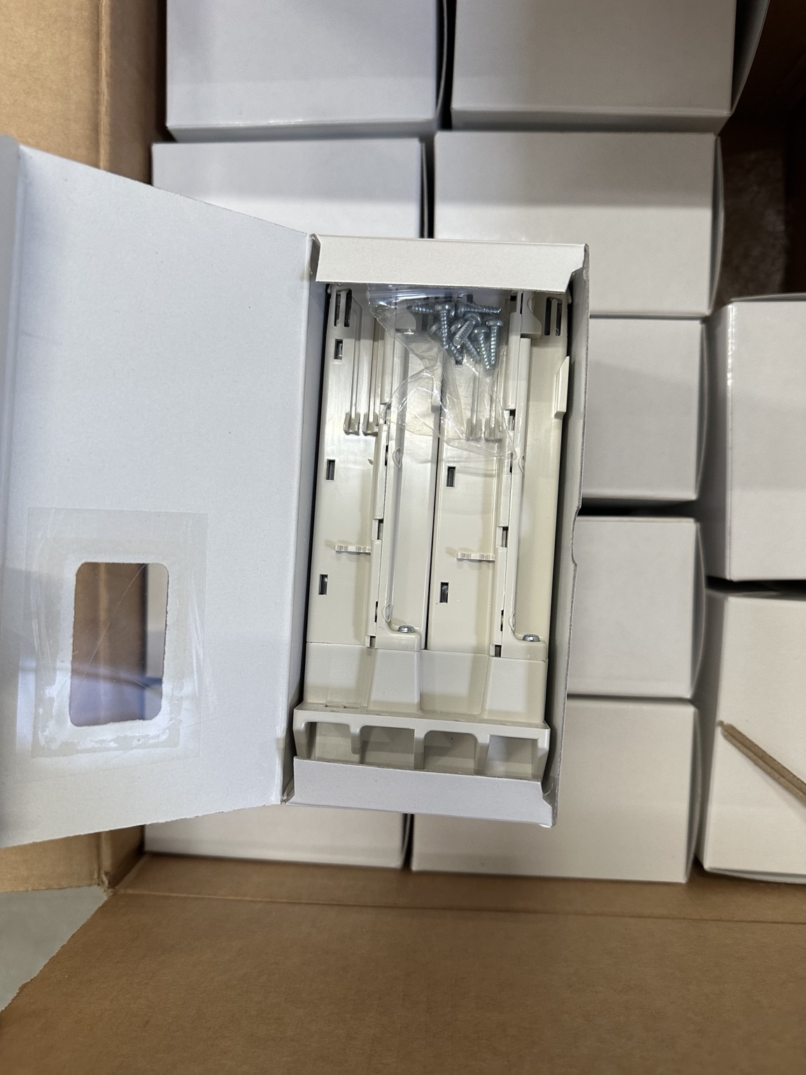
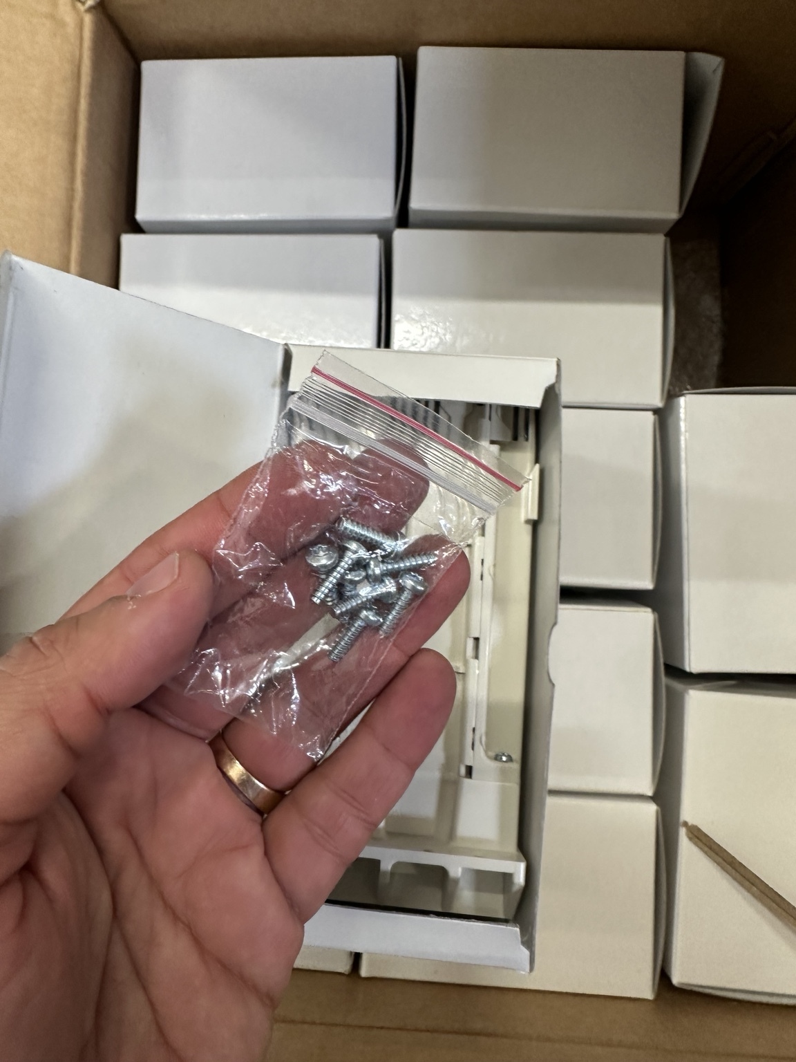
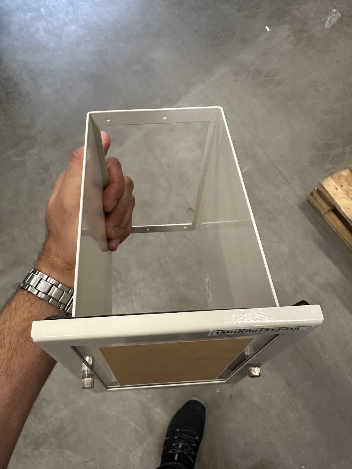
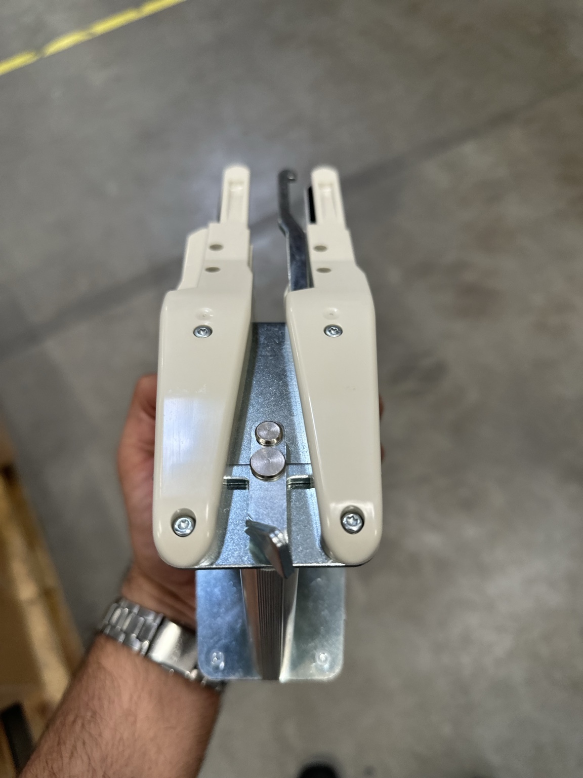
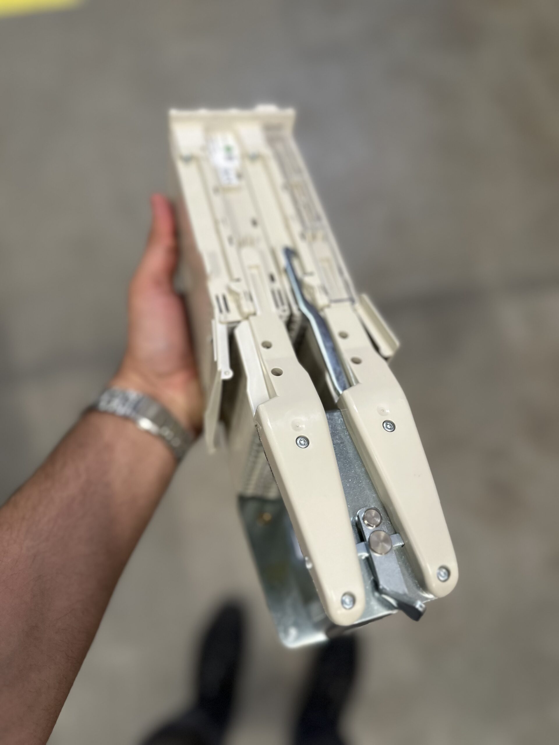
The photographed RTXP 24 was supplied with hardware and separate mounting/enclosure parts. Hitachi Energy identifies 1MRK 000 020-BT as the RTXP 24 mounting kit for a 4U rack assembly. The field photographs also show a metal panel enclosure/cover carrying 1MRK001913-DA; that observed label should be checked against the purchase order and the current regional accessories catalogue before it is used as an ordering reference.
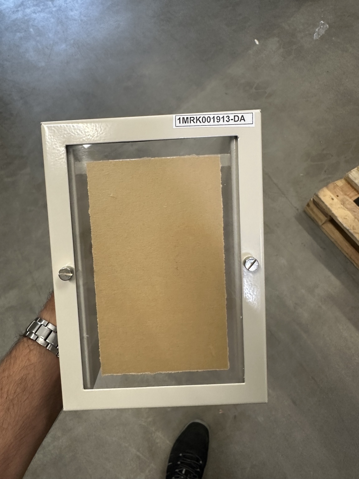
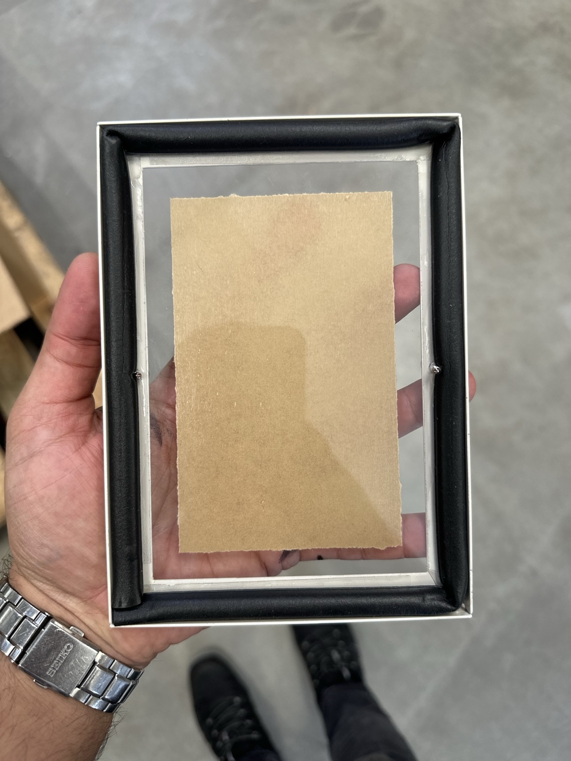
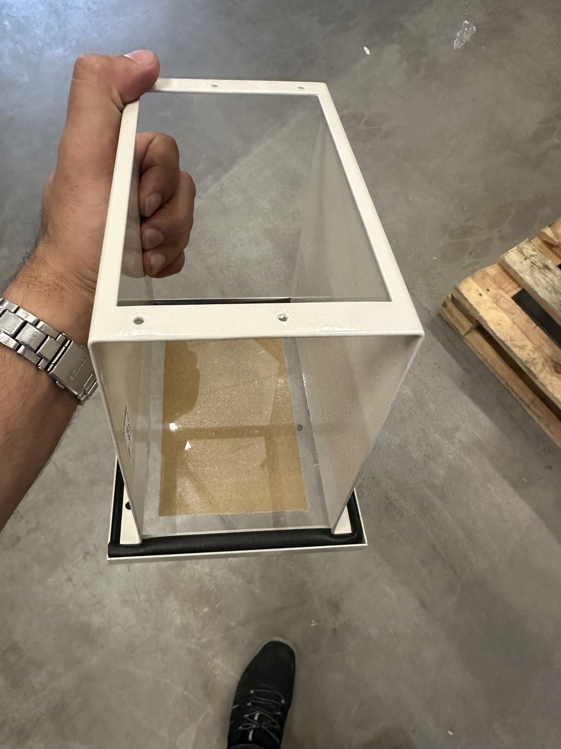
The manufacturer’s RHGP description explains that the light-beige sheet-steel case is inserted through a switchboard cut-out and secured from the front. RTXP 24 requires an extra mounting kit when installed in an RHGP case. Case selection must consider:
- actual panel cut-out and front-space dimensions;
- required rear depth and wire bend radius;
- access for inserting and removing COMBIFLEX sockets;
- segregation from higher-voltage or EMC-sensitive wiring;
- door opening and test-handle operating clearance;
- the declared front protection class and gasket condition;
- mechanical support so plug insertion forces are not transferred to unsupported sheet metal.
Receiving inspection and bench checks
Before the switch is installed or energized, perform and record at least the following:
- model and complete suffix match the approved bill of materials;
- face symbol matches the ordered contact arrangement;
- positions 1–24 and terminals 29–30 are legible;
- both housings, guide rails, doors and latches are undamaged;
- correct mounting kit, case, gasket and screws are present;
- correct socket type and crimp tool are available;
- no loose manufacturing debris or displaced contact is present;
- contact continuity in the normal position matches the symbol catalogue;
- trip contact demonstrates the intended early-break/late-make order;
- each current group shorts before its A–B path opens and restores in the safe reverse order;
- standard contacts isolate and restore correctly;
- 29–30 changes state only under the intended handle operation;
- insulation/withstand checks, if required, follow the manufacturer’s approved method and do not damage connected electronics.
Do not improvise a sequencing test by pressing internal parts with metal tools. Use the correct handle and a controlled de-energized bench setup.
Common faults and troubleshooting
| Symptom | Likely causes | Safe next check |
|---|---|---|
| IED does not enter test mode | 29–30 not wired, wrong BI voltage/polarity, TESTMODE logic not configured, RTXF used instead of RTXH | Check the approved 29–30 circuit and binary-input status |
| CT current remains on the IED after handle insertion | Wrong position assignment, handle not fully inserted, damaged contact, wiring bypasses RTXP | Stop injection/work and prove the CT boundary under the approved procedure |
| CT-side current becomes unstable or voltage appears | Shorting group incomplete, wrong neutral/return, damaged COMBIFLEX socket, open CT secondary | Treat as an unsafe CT condition; do not continue manipulating the switch energized |
| Trip-circuit supervision alarm appears | Expected physical trip isolation, TCS topology, wrong trip-contact assignment or incomplete handle travel | Compare TCS behavior with the test philosophy; confirm all trip paths |
| Breaker or lockout operates during injection | Trip path not isolated, second trip path bypasses RTXP, wrong test lead, logic output not blocked | Stop the test, secure the equipment and investigate the full trip matrix |
| Measured phase/angle is wrong | Channel swap, reversed polarity, wrong common/neutral, test-set return error, incorrect ratio setting | Return outputs to zero and repeat low-level channel-identification checks |
| Handle is difficult to insert | Wrong handle, damaged guides, misalignment, contaminated contacts or distorted mounting | Do not force it; isolate and inspect mechanically |
| Normal values do not return after withdrawal | Handle partly latched, contact/socket damage, forgotten test lead, forced IED state | Keep the bay under test control until full restoration is independently verified |
Manufacturer technical data: how to use it correctly
Hitachi Energy’s current COMBITEST buyer’s guide states the following test-system values:
| Parameter | Manufacturer-stated value |
|---|---|
| Test voltage | 2.5 kV |
| Highest system voltage | 600 V DC; 500 V AC |
| Test contacts | 20 A continuous; 500 A for 1 s |
| Signalling contact | 10 A continuous; 150 A for 1 s |
| Dielectric type test | 5 kV for 1 min, referenced to IEC 61010-2-30 |
| Impulse type test | 6 kV, 1.2/50 μs, 0.5 J, referenced to IEC 60255-5 |
These are not field-test setpoints. Do not apply a dielectric or impulse test to an installed assembly simply because the catalogue lists a type-test value. Connected IEDs, surge suppression, electronics and wiring may require disconnection and a different routine-test method. Likewise, a 20 A contact rating does not make continuous high-current injection through the IED permissible.
Procurement checklist
For a replacement or new design, specify more than “one RTXP 24”:
- complete RTXP order code and suffix;
- approved symbol/contact arrangement;
- wording and function labels required on both front doors;
- RTXH 24-1 test handle and its order code;
- required RTXF, RTXB and RTXM accessories;
- test leads, plugs, COMBIFLEX sockets and crimp tooling;
- mounting kit and exact case/rack arrangement;
- IED type, analog input configuration and CT/VT circuit quantity;
- internal or external neutral requirement;
- single- or three-phase trip philosophy and number of independent trip paths;
- 29–30 TESTMODE voltage, IED input and station indication logic;
- spare-position philosophy and future test requirements;
- current document revision and regional product availability.
Frequently asked questions
Is RTXP 24 a test block or a test switch?
Hitachi Energy calls it a test switch within the COMBITEST system. “Test block” is widely used in field language, but the official name is useful when searching drawings, manuals and order codes.
Does RTXP 24 automatically short every CT circuit?
Only CT conductors routed through correctly configured current-contact positions and the intended shorting group are automatically shorted. A wrong variant, wrong terminal assignment or bypass wiring can defeat the function.
Are positions 1–24 universal across all RTXP 24 units?
No. The physical numbering is common, but the mix of trip, current and general contacts changes with the complete RK 926 315 suffix. Read the face symbol and the manufacturer symbol catalogue for the exact unit.
What are terminals 29 and 30?
They form the normally-open “In test mode” signalling contact. In applicable IED schemes, this contact is wired to the TESTMODE function input. Its logic and binary-input voltage must be commissioned.
Can an ordinary banana plug be inserted into the RTXP contact bank?
No improvised probe should be used. Use the correct COMBITEST handle, plugs and leads. An incorrect pin can spread or damage a socket, defeat sequencing or create an unsafe current path.
Does IED test mode replace physical trip isolation?
No. Test mode is software/configuration behavior. Physical trip isolation and the complete trip matrix must still be verified.
Can RTXP secondary injection prove CT polarity?
It can prove relay-channel response and relative phasors from the RTXP test boundary. It does not by itself prove the polarity of the primary CT installation and all field wiring. Use the required primary/loop/polarity tests.
Which test handle fits RTXP 24?
The current buyer’s guide lists RTXH 24-1, 1MYN000029-CC. Verify the latest ordering document and the installed switch revision before purchasing.
Why does trip-circuit supervision alarm during testing?
The RTXP intentionally opens the trip path. Whether TCS should alarm, be blocked or be test-qualified depends on the TCS topology and project logic. The expected behavior belongs in the test procedure.
Field-photo gallery
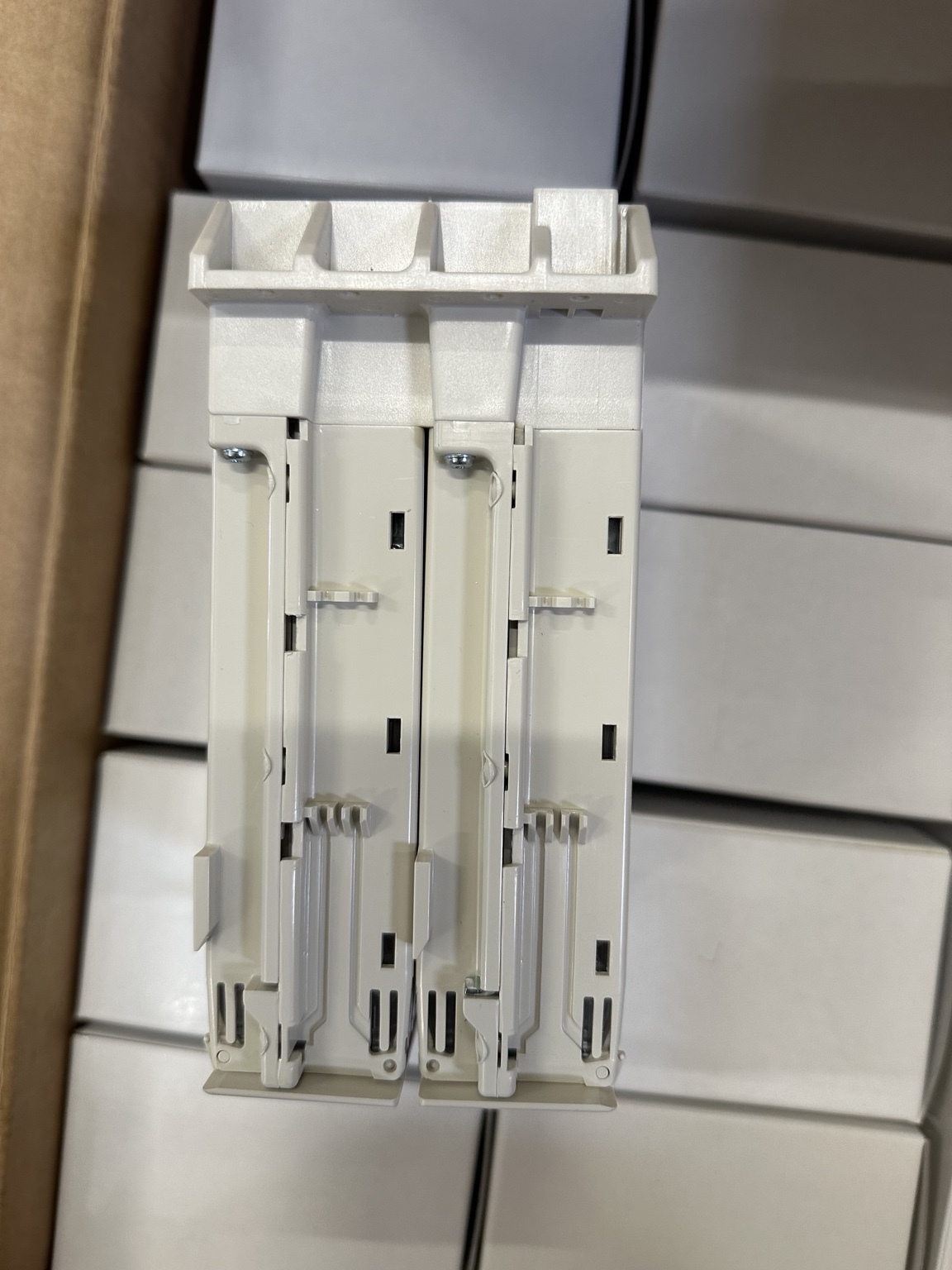
The following photographs document the construction, supplied hardware and panel-mounting arrangement of the inspected RTXP 24. They are included to make component identification easier; they are not dimensional manufacturing drawings.


Related LearnSwitchgear guides
- Protection Relay Secondary-Injection Testing During FAT
- LVC CT Circuits and Safe Test Facilities
- LVC VT Circuits and Isolation
- CT Ratio, Polarity, Continuity and Secondary-Earthing Tests
- Trip-Circuit Supervision for MV Breaker Coils
- Primary Injection and End-to-End Scheme Testing
- How to Specify a Modern Protection Relay Test Set
Editorial record
- Physical unit reviewed: Hitachi Energy RTXP 24, RK 926 315-AK
- Physical photo set: 21 unique original field photographs supplied by the article owner
- Technical verification date: 25 August 2026
- Scope: IEC-oriented protection and control panels using conventional CT/VT and hardwired trip circuits
- Independence: This is an independent engineering guide and is not an installation instruction issued or approved by Hitachi Energy
Official manufacturer sources
- Hitachi Energy — COMBITEST system for relay testing
- Hitachi Energy — COMBITEST RTXP 8-18-24 test switches
- Hitachi Energy — Test System COMBITEST Buyer’s Guide, 1MRK512011-BEN, Revision D
- Hitachi Energy — RTXP 24 Symbol Catalogue, 1MRK001024-CA
- Hitachi Energy — 670/650 Series and SAM600-IO IEC Accessories Product Guide, 1MRK514012-BEN, Revision L
- Hitachi Energy — Relay accessories and RHGP/RHGS/RHGX case systems
- Hitachi Energy — 670 series IEC Installation Manual, 1MRK514026-UEN, Revision R
- Hitachi Energy — REC670 IEC Commissioning Manual, 1MRK511403-UEN, Revision P
Engineering note: Always verify the exact manufacturer-document revision, product variant, IED hardware, project drawings, CT/VT earthing philosophy, trip matrix, national rules and site procedures. Product data and order codes may vary by region or revision.