

Executive answer
Fast fault clearing is normally desirable, but a circuit breaker is not better merely because its measured opening time is smaller. The correct objective is to interrupt the required current, within the declared time envelope, with the required dielectric recovery, contact travel, pole synchronism, mechanical damping, and repeatability.
The most important conclusions are:
- IEC 62271-100 does not impose one universal opening-time limit for every medium- and high-voltage circuit breaker. Time values are design-specific and are assigned by the manufacturer, verified by applicable type/routine tests, and stated in product documentation.
- Opening time is not the same as breaking or interrupting time. Opening time ends when the arcing contacts have separated; breaking time ends only after current has been extinguished in all poles.
- In an AC breaker, current interruption normally occurs at a suitable current zero. Earlier contact separation therefore does not always produce an equal reduction in total clearing time.
- The manufacturer’s minimum opening time is technically important. It affects the DC component of the short-circuit current remaining at contact separation. A breaker that has been modified to open substantially faster can face a more severe asymmetrical current duty than the duty used for its rating or type-test basis.
- Excessive operating velocity, incorrect damping, contact rebound, excessive pole spread, insufficient contact travel, or an incorrect close-open sequence can make a fast-looking breaker unsafe.
- Acceptance must be based on the breaker type, mechanism, release, control voltage, temperature, interrupting technology, application, and manufacturer limits – not on a generic internet value such as “30 to 60 ms.”
- IEC minimum control-voltage requirements are operation requirements, not a universal requirement that the rated-voltage opening-time range must also be met at the minimum voltage. Unless the manufacturer or project specification declares a timing limit at reduced voltage, successful operation and timing acceptance must be assessed separately.
1. The complete fault-clearing chain
The power system remains exposed to fault current until the protection system detects the fault, issues a trip command, the breaker mechanism separates its contacts, and the interrupter successfully extinguishes the arc.
The total fault-clearing time can be written as:
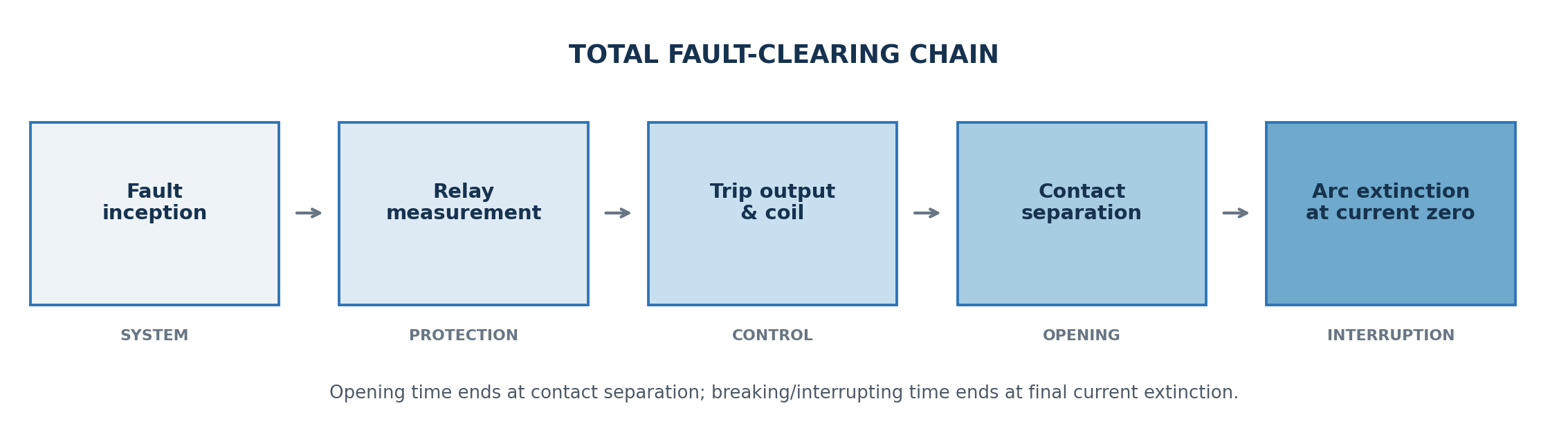
For practical protection studies, the first three terms are often grouped as the protection operating time, while the last two are grouped as the breaker interrupting or breaking time.
1.1 Why every millisecond can matter
Reducing legitimate clearing time can:
- reduce thermal stress, which broadly follows an I^2t relationship;
- reduce electrodynamic stress duration;
- reduce arc-flash incident energy when the arcing current and geometry are otherwise unchanged;
- improve transient stability and critical clearing margin;
- reduce voltage depression and disturbance propagation;
- reduce damage at the fault location.
However, these benefits apply to successful interruption. A fast mechanism that produces inadequate contact gap at current zero, unstable pole behavior, severe rebound, or operation outside its type-tested envelope is not an improvement.
2. Timing terms that must not be confused
2.1 Opening time
For a shunt-trip operated breaker, opening time is the interval from energization of the opening release to separation of the arcing contacts in all poles. It includes the electrical and mechanical delays internal to the breaker, such as:
- trip-coil current build-up;
- armature movement;
- latch release;
- release of stored mechanical energy;
- linkage motion up to contact separation.
An offline timing analyzer normally measures a contact-state transition. Depending on the breaker construction and measurement method, this transition must be correctly associated with the relevant main or arcing contact event.
2.2 Contact-parting time
In IEEE practice, contact-parting time is commonly used for the interval from trip-circuit energization to parting of the breaker contacts. The precise test definition and reference contact must be taken from the applicable standard and manufacturer documentation.
2.3 Arcing time
Arcing time is the interval between arc initiation after contact separation and final arc extinction. It is influenced by:
- the instant of contact separation relative to the current waveform;
- power frequency;
- short-circuit asymmetry and delayed current zeros;
- interrupter type and contact material;
- contact gap and velocity through the arcing zone;
- gas flow, pressure, vacuum-interrupter behavior, and dielectric recovery;
- transient recovery voltage (TRV).
Arcing time cannot be established from a normal no-load contact timing test alone.
2.4 Break time or interrupting time
Break time is the interval from initiation of the opening operation to final current interruption in all poles. In simplified form:
t_break = t_opening + t_arcing
IEEE defines rated interrupting time as a maximum permissible interval under stated control-voltage and mechanism conditions. IEC and IEEE terminology must not be mixed without checking the exact edition and product documentation.
2.5 Relay time, breaker time, and total clearing time
Protection relay event records often provide the time from fault pickup to trip output. A breaker analyzer provides time from a command reference to a contact event. A disturbance recorder can show current extinction. These are different measurements.
For a defensible investigation, align all clocks and identify:
- fault inception;
- relay pickup and operate;
- trip output contact operation;
- voltage at the trip-coil terminals;
- trip-coil current initiation;
- 52a/52b auxiliary-contact transitions;
- main-contact separation;
- current extinction in each phase.
2.6 Closing time
Closing time is normally measured from energization of the closing circuit to contact touch in all poles. Closing performance affects:
- short-circuit making duty;
- prestrike and switching transients;
- close-open (trip-free) performance;
- synchronism between poles;
- anti-pumping and interlock logic;
- controlled switching applications.
2.7 Close-open, open-close, dead time, and reclosing time
- C-O time: interval associated with a closing operation followed by opening. It is critical for trip-free performance.
- O-C time: interval associated with opening followed by reclosing.
- Dead time: the intentional interval during which the circuit remains open before reclosing.
- Reclosing time: includes breaker and control-system behavior required to re-establish current.
- Make-break time: extends from current initiation during closing to final arc extinction during the subsequent opening operation.
These quantities are not interchangeable. A compliant 0.3 s auto-reclose sequence does not mean the mechanical opening time is 0.3 s.
2.8 Pole spread and contact scatter
Pole spread is the difference between the earliest and latest corresponding contact event. Excessive spread can:
- increase negative- and zero-sequence exposure;
- alter first-pole-to-clear TRV duty;
- cause abnormal current interruption sequence;
- affect motors, generators, transformers, and sensitive process loads;
- undermine controlled switching.
The acceptable value is product-specific. Siemens, for example, declares a synchronism error of no more than 2 ms for the SION 3AE6 cited later; an OMICRON diagnostic example uses 2.7 ms. Neither value should be applied universally.
3. What IEC and IEEE actually require
3.1 Applicable standards
The main references for AC breakers above 1 kV are:
- IEC 62271-100:2021+A1:2024, high-voltage AC circuit-breakers;
- IEC 62271-1:2017+A1:2021, common specifications;
- IEC/IEEE 62271-37-013:2021 for generator circuit-breakers;
- IEEE C37.04-2018, together with IEEE C37.04a-2025 where contractually applicable, for ratings and requirements;
- IEEE C37.09-2018, together with IEEE C37.09a-2025 where contractually applicable, for test procedures.
Always use the contractually specified edition. A project may legitimately reference an earlier edition, but the deviation must be understood.
3.2 There is no universal IEC minimum or maximum opening time
IEC defines timing quantities, ratings, duties, test conditions, and operating sequences. It does not say that every 12 kV, 24 kV, 36 kV, vacuum, SF6, GIS, AIS, distribution, or generator breaker must open within the same numerical range.
The acceptance hierarchy should be:
- serial-number-specific factory routine data and approved project documentation;
- the current manufacturer instruction manual and technical catalogue for the exact breaker and release;
- the manufacturer’s type-test basis and declared minimum/maximum timing values;
- the commissioning fingerprint recorded under controlled conditions;
- fleet trend data for identical breakers;
- generic industry ranges, used only as diagnostic guidance.
3.3 Rated operating sequences
Common IEC operating sequences include:
- O – 3 min – CO – 3 min – CO;
- O – 0.3 s – CO – 3 min – CO;
- O – 0.3 s – CO – 15 s – CO.
The exact duty must be declared for the breaker. A generator breaker or a special rapid-reclosing application may have a different sequence.
3.4 Control-voltage operating ranges
For typical IEC MV/HV applications, manufacturer documentation based on IEC requirements commonly gives:
- closing release and charging motor: 85% to 110% of rated supply voltage;
- DC shunt-opening release: 70% to 110%;
- AC shunt-opening release: 85% to 110%.
These are guaranteed operating ranges, not permission to energize a coil indefinitely. Minimum command duration, duty cycle, coil heating, and maximum pulse duration remain product-specific.
3.5 What IEC does – and does not – require at minimum control voltage
This distinction is essential:
- the IEC operating-voltage requirement for a shunt-opening release establishes that the release and breaker must operate at the applicable lower voltage – commonly 70% of rated voltage for a DC shunt-opening release;
- it does not, by itself, state that an opening-time range declared at rated control voltage must remain unchanged or be met at the lower voltage;
- IEC does not provide one universal maximum permissible opening-time extension at 70% voltage for every breaker design;
- a time limit at minimum voltage becomes binding only when it is explicitly declared by the manufacturer, established by an approved project specification, or supported by agreed type/routine/commissioning data for that breaker.
This is also how product documentation must be read. The Siemens SION 3AE6 catalogue, for example, labels its timing table “Operating times at rated voltage of the secondary circuit” and separately declares the DC shunt-release tripping range as 70% to 110% of rated voltage. The two statements must not be combined into an unsupported conclusion that the rated-voltage opening-time limit automatically applies throughout the complete voltage range.
At reduced coil voltage, slower trip-coil current build-up and armature/latch release can increase the measured opening time. In a stored-energy spring mechanism, the opening spring supplies the main mechanical movement after unlatching, so reduced voltage may affect the electrical/latch-delay portion more strongly than the later travel portion. Magnetic actuators, electronic coils, hydraulic/pneumatic mechanisms, and capacitor-fed drives can behave differently.
Therefore, report reduced-voltage results in two layers:
- IEC operation check: did the breaker successfully complete the commanded operation at the specified voltage measured at the coil terminals?
- Timing check: is there an OEM- or contract-declared time limit for that same voltage, temperature, pressure, mechanism state, and command duration?
If the answer to the second question is no, do not reject the breaker merely because its 70%-voltage opening time is outside a timing range published for rated voltage. Record the value diagnostically, compare phases and traces, trend it, and request an OEM limit where the protection study needs a guaranteed worst-case value.
3.6 IEEE cycle-rated interrupting times
IEEE/ANSI equipment is frequently described as a three-cycle or five-cycle breaker. At 60 Hz:
| Nominal description | Time at 60 Hz | Time represented by same cycle count at 50 Hz |
|---|---|---|
| 2 cycles | 33.3 ms | 40 ms |
| 3 cycles | 50 ms | 60 ms |
| 5 cycles | 83.3 ms | 100 ms |
Do not convert a catalogue rating blindly. Modern IEEE ratings may be stated directly in milliseconds, and the applicable standard/product documentation controls. Eaton’s 27 kV VacClad-W guide, for example, offers 50 ms and 83 ms interrupting-time versions and separately lists contact-parting and arcing-time ranges.
4. Why the minimum opening time matters
This is one of the most overlooked points in breaker application engineering.
The DC component of a short-circuit current decays approximately exponentially. For a simplified worst-case representation:
where:
- T_open,min is the breaker minimum opening time;
- T_relay is the assumed protection operating time used for the rating/test basis;
- tau is the system DC time constant.
For a conventional MV reference case with tau = 45 ms and T_relay = 10 ms:
| Minimum opening time | Total time to contact separation | Remaining DC component | Approx. asymmetrical RMS factor* |
|---|---|---|---|
| 60 ms | 70 ms | 21.1% | 1.044 |
| 45 ms | 55 ms | 29.5% | 1.084 |
| 33 ms | 43 ms | 38.4% | 1.138 |
| 30 ms | 40 ms | 41.1% | 1.157 |
| 20 ms | 30 ms | 51.3% | 1.236 |
| 10 ms | 20 ms | 64.1% | 1.381 |
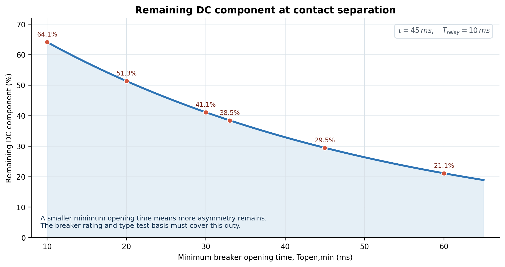
Using the simplified relationship Iasym / Isym = √[1 + 2(%DC/100)²].
This does not mean that a purpose-designed 20 ms breaker is bad. It means that a breaker must be type-tested and rated for the asymmetrical duty corresponding to its designed minimum opening time and the relevant system time constant.
4.1 Worked example
Assume:
- symmetrical short-circuit current = 31.5 kA;
- tau = 45 ms;
- relay time used for the rating basis = 10 ms.
If T_open,min = 45 ms, %DC is approximately 29.5%, and the simplified asymmetrical RMS current is approximately:
31.5 x 1.084 = 34.1 kA
If an unauthorized mechanism modification reduces T_open,min to 20 ms, %DC increases to approximately 51.3%, and the simplified asymmetrical RMS current becomes:
31.5 x 1.236 = 38.9 kA
The symmetrical rating has not changed, but the breaker may now separate its contacts while a materially higher DC component remains. This is why “make it faster” is not a valid field modification strategy.
4.2 Generator and low-resistance systems
Generator circuits may have longer DC time constants and delayed current zeros. Distribution breakers must not automatically be applied as generator breakers merely because voltage and symmetrical current ratings appear adequate. IEC/IEEE 62271-37-013 addresses the distinct duties of generator breakers.
5. Is a faster breaker always better?
5.1 When faster is genuinely beneficial
A faster, properly designed breaker can reduce:
- system fault-clearing time;
- conductor and busbar thermal stress;
- fault damage and arc duration;
- arc-flash exposure;
- instability risk;
- voltage sag duration;
- required breaker-failure protection margins, when the complete scheme is re-engineered.
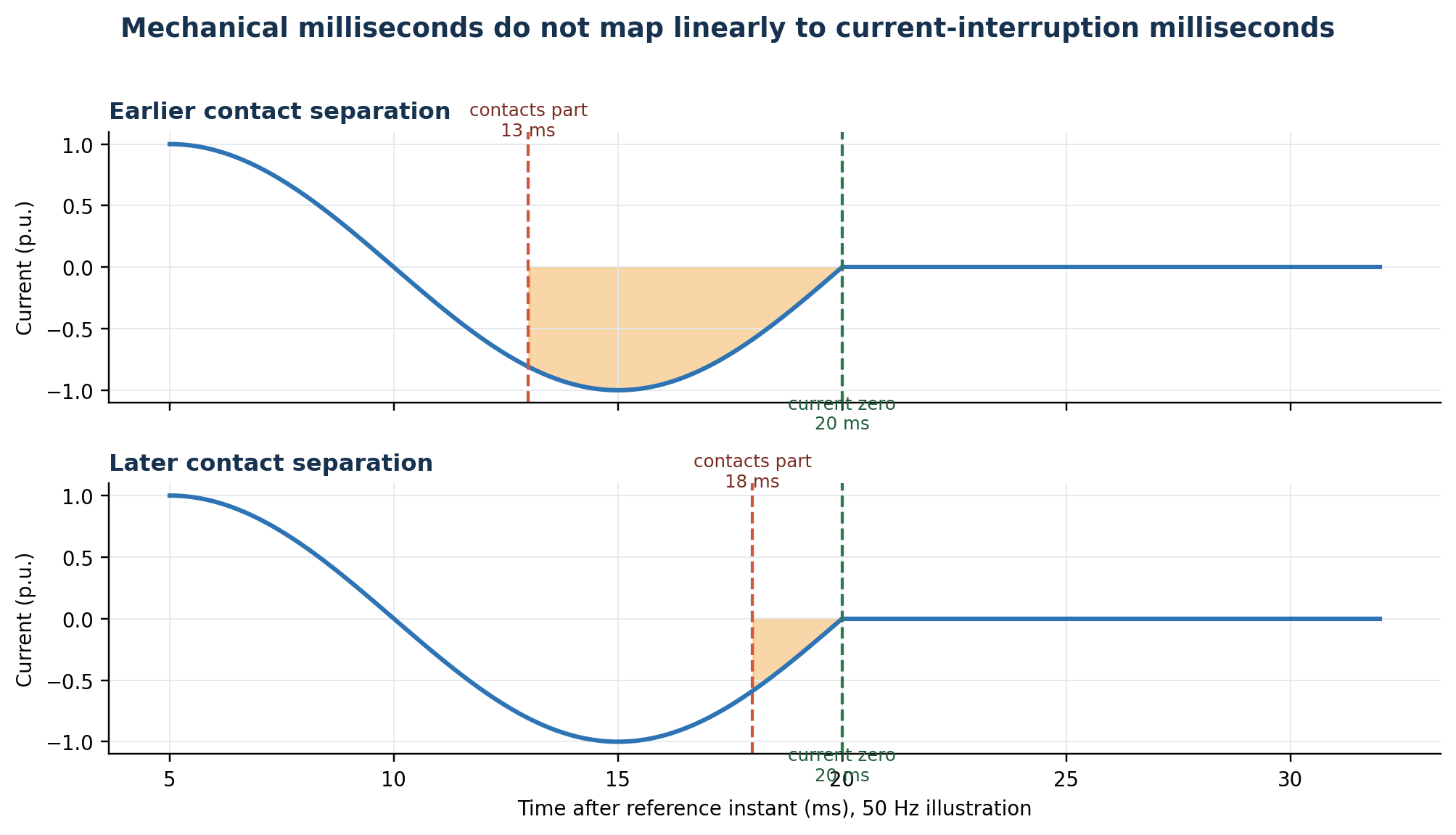
5.2 Why faster contact separation does not guarantee proportionally faster current interruption
An AC vacuum or gas breaker normally interrupts at a suitable current zero. At 50 Hz, successive half-cycle current zeros are 10 ms apart; at 60 Hz they are about 8.33 ms apart.
If the contacts part just before a current zero and the interrupter has developed sufficient dielectric strength, current may be interrupted at that zero. If contacts part just after a current zero, the arc may persist until a later zero. Consequently, a 5 ms reduction in mechanical opening time may:
- reduce breaking time by nearly a half-cycle;
- produce little reduction at all;
- change which pole clears first;
- change the arcing-time duty.
The type-test program therefore evaluates the required arcing-time and TRV duties, not only a no-load stopwatch value.
5.3 Dielectric recovery and TRV
After current zero, the voltage across the open breaker rises as the power system recovers. The breaker must develop dielectric strength faster than the applied TRV. Successful interruption depends on:
- contact gap at current zero;
- contact velocity through the arcing zone;
- cooling and deionization of the arc path;
- vacuum-interrupter dielectric recovery or gas flow;
- TRV peak and rate of rise;
- first-pole-to-clear factor;
- circuit configuration and system grounding.
A fast initial movement is useful only if the complete motion profile provides the required gap, gas flow, and damping. An arbitrarily modified mechanism can invalidate that coordination.
5.4 Mechanical energy, damping, and rebound
Stored-energy mechanisms accelerate substantial moving mass within a few milliseconds. The mechanism must then decelerate safely. Excessive velocity or defective damping can cause:
- overtravel and rebound;
- main-contact or auxiliary-contact bounce;
- shock loading of linkages, pins, bearings, interrupter bellows, and insulating rods;
- loss of contact-travel calibration;
- accelerated wear or fracture;
- inconsistent pole timing;
- failure to remain in the commanded position.
This is why timing alone is insufficient. Travel, velocity in the arcing zone, overtravel, rebound, contact wipe, and damping must be assessed together.
5.5 Close-open and trip-free behavior
During a C-O operation, an opening command may exist while the breaker is closing. The breaker must not repeatedly close and open (“pump”), and it must complete the required trip-free duty.
For some puffer-type gas breakers, an excessively short C-O dwell can prevent the interrupter from developing the pressure/geometry required for the subsequent interruption. The required minimum C-O time and auxiliary-switch adjustment are therefore design-specific.
5.6 Current chopping and switching overvoltages
Vacuum interrupters can interrupt small inductive currents before the natural current zero, producing current chopping and overvoltage. Motors, unloaded transformers, and reactors can be sensitive to:
- current chopping;
- multiple restrikes;
- virtual current chopping;
- high-frequency escalation;
- steep-front overvoltages.
It is inaccurate to claim that mechanical opening speed alone causes current chopping. Contact material, interrupter design, current magnitude, circuit capacitance/inductance, and switching instant are major factors. Appropriate remedies include:
- surge arresters located near the protected equipment;
- RC surge suppressors where engineering studies support them;
- controlled switching where technically applicable;
- a breaker specifically proven for the switching duty;
- cable and grounding design appropriate to the transient study.
Do not intentionally slow a fault breaker as a substitute for a proper transient solution unless the breaker manufacturer has engineered and approved that arrangement.
5.7 Protection selectivity and scheme timing
A substantial change in breaker time affects:
- overcurrent grading margins;
- zone-selective interlocking assumptions;
- breaker-failure protection timers;
- auto-reclose dead time;
- bus-transfer logic;
- synchronism-check and controlled switching;
- arc-flash study clearing times;
- process interlocks using 52a/52b contacts.
Normally, a faster breaker does not harm breaker-failure protection, because current disappears sooner. However, auxiliary-contact logic can behave incorrectly if 52a/52b timing or bounce changes. Any material timing change requires scheme review.
6. Manufacturer values: examples, not universal limits
The following values demonstrate why generic acceptance numbers are unsafe.
| Manufacturer/product | Opening/contact-parting | Arcing and break/interrupting time | Closing time and key note |
|---|---|---|---|
| Siemens SION 3AE6 | ≤30 ms with first/second shunt release; ≤45 ms with further releases | Arcing <15 ms; break ≤45 ms or ≤60 ms depending on release | Closing ≤60 ms; synchronism error ≤2 ms; minimum trip impulse >10 ms for primary shunt releases |
| ABB VD4, 2024 catalogue | 33-60 ms | Arcing 10-15 ms; break 43-75 ms | Closing 50-80 ms; exact value depends on variant |
| Eaton VCP-W, 27 kV | 30-45 ms for standard five-cycle; 30-38 ms for optional three-cycle | Arcing 5-17 ms; rated interrupting time 83 ms or 50 ms | Closing 45-60 ms; catalogue explicitly separates contact-parting, arcing, and interrupting time |
| ABB VD4G-50 generator breaker | Not separately declared in the cited data sheet | Total breaking time ≤61 ms | Generator breaker designed for increased DC component, delayed current zeros, and generator TRV duty |
These examples prove three points:
- opening and break time are different;
- the release type can change the timing limit;
- the correct range is a property of the complete breaker design and application.
7. Complete breaker specification checklist
7.1 Primary electrical ratings
Verify at least:
- rated voltage Ur;
- rated frequency fr;
- rated insulation level, including power-frequency withstand Ud and lightning impulse withstand Up;
- rated continuous current Ir;
- rated short-time withstand current Ik and duration tk;
- rated peak withstand current Ip;
- rated short-circuit breaking current Isc;
- rated short-circuit making current;
- DC component and associated time constant;
- TRV envelope and rate of rise;
- first-pole-to-clear factor;
- out-of-phase making and breaking capability;
- cable/line charging and capacitor-bank switching capability;
- small inductive current switching duty;
- generator-source duty where applicable.
7.2 Classification and endurance
Confirm the required IEC classes and application, including as applicable:
- mechanical endurance class M1 or M2;
- electrical endurance class E1 or E2;
- capacitive switching class C1 or C2;
- system/application class such as cable- or line-system duty;
- number of permissible operations at rated current and at short-circuit current;
- maintenance interval and allowed interruption wear.
7.3 Operating mechanism and control ratings
Specify:
- mechanism type: spring, magnetic actuator, hydraulic, pneumatic, or other;
- rated trip- and close-coil voltage and AC/DC supply;
- guaranteed operating-voltage range;
- coil power, inrush current, hold current, and permissible energization duration;
- minimum command duration;
- opening and closing spring charging time;
- charging-motor current signature and duty;
- anti-pumping provision;
- trip-free behavior;
- first and second trip coils where required;
- undervoltage release behavior and delay;
- auxiliary-contact quantity, duty, and timing;
- supervision compatibility with the protection relay TCS circuit.
7.4 Timing and motion values to demand from the supplier
The procurement specification should require the manufacturer to declare:
- minimum, nominal, and maximum opening time;
- applicable release and control voltage for each value;
- the reference control voltage for every declared timing value;
- where the project requires it, a separately guaranteed maximum opening/breaking time at the specified minimum DC voltage and adverse service condition – clearly identified as a purchaser/OEM requirement, not a generic IEC timing limit;
- closing time;
- arcing-time range and total break time;
- C-O and O-C times;
- rated operating sequence;
- pole spread for opening and closing;
- auxiliary-contact timing relative to main contacts;
- total travel/stroke;
- contact wipe or penetration;
- opening and closing velocity windows, including the measurement points;
- overtravel, rebound, and bounce limits;
- mechanism damping criteria;
- minimum pick-up voltage and test method;
- acceptable repeatability and temperature range;
- factory routine timing results for each serial number.
7.5 Environmental and installation parameters
Check:
- ambient temperature and temperature-dependent mechanism limits;
- altitude and insulation correction;
- humidity, condensation, pollution, and corrosion class;
- seismic and vibration requirements;
- gas density/pressure alarms and lockouts for gas breakers;
- heater and anti-condensation supply;
- indoor/outdoor enclosure and IP rating;
- orientation and mounting constraints;
- mechanical loads at terminals and bushings;
- withdrawable-truck interlocks and secondary-plug logic.
8. Testing with OMICRON CIBANO 500
OMICRON CIBANO 500 combines a timing/travel analyzer, micro-ohmmeter, and adjustable AC/DC coil/motor supply. Its PTM software and Circuit Breaker Testing Library (CBTL) support asset-specific test plans and comparison with manufacturer or user-defined limits.
8.1 Relevant CIBANO 500 capabilities
According to the current OMICRON brochure, the system supports:
- main and auxiliary contact timing;
- resistance- or voltage-threshold timing;
- Current Sensor Measurement (CSM) for both-sides-grounded GIS timing;
- Voltage-based Timing Measurement (VTM) for suitable sealed MV GIS;
- first-trip measurement using trip-coil and CT secondary signals;
- static contact resistance up to 100 A injection;
- dynamic resistance measurement;
- trip- and close-coil current signatures;
- motor current and spring-charging time;
- minimum pick-up testing;
- undervoltage condition and undervoltage-release testing;
- motion/travel, velocity, wipe, overtravel, rebound, and damping assessment with suitable transducers.
Selected instrument data include an auxiliary-input sample rate up to 40 kHz, 25 microsecond minimum resolution, adjustable DC output up to +/-300 V, AC output up to 240 V, and a 20 kg main unit. Always verify the exact configuration and accessory set before planning the test.
8.2 Test preparation
Before connection:
- Identify the exact breaker type, serial number, mechanism, interrupter, trip coil, close coil, and rated control voltage.
- Obtain the manufacturer timing/travel limits and factory routine report.
- Record the as-found state, ambient temperature, mechanism pressure, spring state, operation counter, and time since last operation.
- Review the switching program and operating limits so coils are not overheated.
- Isolate, lock out, test for absence of voltage, and earth according to the approved safety procedure.
- For HV equipment, use a both-sides-grounded method where required by the safety procedure and supported by the selected measurement technique.
- Confirm whether the test reference is test initiation, voltage at coil terminals, or coil-current pickup.
8.3 First-trip test: do this before exercising the breaker
A breaker that has remained closed for months or years can be slow on the first operation because of degraded lubricant, corrosion, contamination, or increased static friction. Repeated operations can temporarily improve the time and conceal the problem.
The first-trip test should therefore be captured before any maintenance exercise operation. OMICRON notes that CT-current-based first-trip timing includes arcing time. Label this result accordingly; do not compare it directly with a no-load opening-time limit.
8.4 Recommended offline test sequence
After the first-trip assessment and safe isolation:
- O test at rated voltage: measure all main contacts, trip-coil current, actual coil-terminal voltage, and auxiliary contacts.
- C test at rated voltage: measure closing time, pole spread, close-coil current, contact bounce, and spring state.
- O-C test: verify reclosing/dead-time performance where the breaker is rated for it.
- C-O test: verify trip-free behavior, dwell time, anti-pumping logic, and auxiliary-switch adjustment.
- Reduced-voltage operation tests: after confirming the exact release and command-duration requirements, verify successful operation at the applicable lower voltage – commonly 70% DC for a shunt-opening release and 85% for a closing release. Record timing and coil/travel traces, but apply a timing pass/fail limit only when the OEM or project documentation explicitly assigns that limit to the test voltage.
- Minimum pick-up test: use short controlled pulses and sufficient cooling time to avoid coil damage.
- Motion/travel test: measure total travel, wipe, velocity in the manufacturer’s defined arcing zone, overtravel, rebound, and damping.
- Static contact resistance: compare phases and historical values using the OEM connection method.
- Dynamic resistance test, where applicable: correlate resistance transitions with motion and contact events.
- Motor test: record inrush, steady-state current, charging time, end-of-charge behavior, and supply voltage.
8.5 What must be included in the report
The report should contain:
- breaker identification and serial number;
- test date, temperature, state, and mechanism pressure;
- instrument, firmware/software, modules, transducers, and calibration status;
- wiring/measurement method and whether both sides were grounded;
- command voltage at the breaker terminals, not only the test-set setting;
- traces for main contacts, auxiliary contacts, coil current, motor current, and travel;
- opening/closing time for every pole and interrupter;
- pole spread, repeatability, C-O/O-C results;
- travel, velocity reference points, wipe, overtravel, rebound, and damping;
- static/dynamic resistance results;
- first-trip result clearly separated from exercised offline results;
- manufacturer limits and the exact document revision used;
- deviations, diagnosis, corrective action, and final retest.
9. Interpreting a breaker that is too slow
9.1 Common causes
- low DC voltage at the trip-coil terminals under load;
- high-resistance trip-circuit connection or undersized wiring;
- incorrect trip coil or coil damage;
- sticky armature, latch, or hardened lubricant;
- corrosion, contamination, or foreign material;
- weak or incorrectly charged opening spring;
- excessive friction or misaligned linkage;
- hydraulic/pneumatic pressure deficiency;
- incorrect dashpot behavior;
- excessive mechanism temperature sensitivity;
- test reference or trigger error.
9.2 Corrective approach
- Verify the measurement definition and wiring.
- Measure actual coil-terminal voltage and coil current during operation.
- Compare first-trip and subsequent traces.
- Analyze coil signature to separate electrical delay, latch delay, and mechanism travel delay.
- Measure motion/travel and check the arcing-zone velocity.
- Inspect and service only in accordance with the OEM manual.
- Retest timing at rated control voltage; separately verify operation at the applicable minimum control voltage. Apply a reduced-voltage timing criterion only if it is explicitly declared for that condition.
- Review breaker-failure timer and arc-flash calculations until the defect is resolved.
Never “correct” a slow breaker merely by shortening the protection relay delay. That masks a mechanical defect and reduces coordination margin without restoring interrupting performance.
10. Interpreting a breaker that appears too fast
10.1 First rule: confirm that it is really too fast
Check for:
- wrong start trigger;
- use of a 52a/52b transition instead of the main contact;
- incorrect wet/dry contact threshold;
- measurement of a pre-insertion resistor contact;
- wrong breaker template in the test software;
- transducer polarity or motion conversion error;
- a warmed/exercised mechanism being compared with an as-found factory value;
- incorrect rated coil voltage entered in the test set.
10.2 Possible physical causes
- excessive control voltage or wrong coil rating;
- incorrectly adjusted or replaced opening spring;
- latch-clearance or linkage adjustment error;
- missing, bypassed, or worn damping component;
- incorrect hydraulic/pneumatic pressure;
- wrong spare parts or non-OEM modification;
- auxiliary-switch maladjustment during C-O operation;
- excessive rebound that produces an early apparent contact event.
10.3 Corrective actions
- restore the exact rated control voltage and verify it at the coil terminals;
- compare coil-current and travel traces with factory/commissioning fingerprints;
- verify opening velocity at the OEM-defined points, not as an arbitrary average;
- inspect springs, latch, linkages, buffers/dashpots, and mechanism pressure;
- confirm contact wipe, stroke, overtravel, rebound, and pole spread;
- restore manufacturer settings and approved parts;
- repeat O, C, C-O, and O-C operations under controlled conditions;
- review the type-test minimum opening-time/DC-component basis;
- revalidate protection coordination, breaker-failure logic, and auxiliary-contact logic.
Do not add an intentional relay delay simply to force the total clearing time back to a familiar value. If the breaker is mechanically outside its declared range, the mechanism must be corrected. If the breaker is a purpose-designed faster replacement, the complete application and protection study must be updated.
11. Practical acceptance matrix
| Observation | Engineering interpretation | Required action |
|---|---|---|
| Time is within the exact OEM range; travel and coil signatures are normal | Acceptable, subject to repeatability and other tests | Record as baseline and trend |
| Time is below a published maximum but no minimum is supplied | Not automatically “better” | Compare with factory data, velocity, damping, and OEM guidance |
| One pole differs materially from the others | Possible linkage, pole mechanism, or measurement issue | Repeat test, check connections, then inspect pole mechanism |
| First trip is slow but later operations are normal | Classic idle-time degradation indication | Investigate lubrication, corrosion, contamination; do not accept exercised result alone |
| Opening time is normal but current extinction is late | Arcing/TRV/current-zero/application issue | Review disturbance record, breaker duty, arcing time, and application rating |
| Auxiliary contact changes early/late while main timing is normal | 52a/52b adjustment or bounce problem | Correct auxiliary switch and revalidate scheme logic |
| Timing is fast but rebound/overtravel is excessive | Damping or mechanism-energy problem | Remove from service as required and service per OEM |
| Timing changes strongly with control voltage | May be expected to some degree, but can also indicate supply, coil, latch, or mechanism margin issues | Verify operation at the IEC/OEM voltage limit; compare timing only with a limit declared for that voltage; analyze coil and travel signatures |
| Pole timing is good but static resistance is high | Contact path/connection problem | Inspect primary contacts, joints, wipe, and contact condition |
12. Protection and system-study considerations
12.1 Breaker-failure protection
A typical breaker-failure timer must exceed the worst credible sum of:
- trip output and interposing relay delay;
- the worst credible breaker opening/breaking time for the lowest credible trip-circuit voltage and adverse temperature, taken from OEM data, an agreed project test, or a justified engineering allowance – not automatically from the rated-voltage timing table;
- current-detector reset time;
- logic and output time for retripping or backup tripping;
- an engineering security margin.
Use interrupting/current-extinction time when the breaker-failure element is current-based. Do not use a no-load opening time without adding the applicable arcing and detection margins.
12.2 Arc-flash studies
Use the total protection-plus-breaker clearing time appropriate to the arcing current. If instantaneous protection may not pick up at the calculated arcing current, a faster nameplate breaker time does not compensate for the relay delay.
12.3 Coordination studies
Grading intervals should include breaker operating-time variation, relay overtravel/reset behavior, CT performance, communication time, and margin. If a breaker is replaced by a much faster design, verify selectivity rather than assuming the change is always harmless.
12.4 Auto-reclosing and bus transfer
Confirm:
- rated operating sequence;
- mechanical readiness and spring recharge;
- dead time;
- deionization and transient requirements;
- synchronism-check logic;
- motor residual voltage and phase angle for transfer schemes;
- interlocks and anti-pumping.
13. A procurement clause that prevents future disputes
A strong specification can include the following requirement:
For critical applications, add:
- first-trip acceptance requirements;
- breaker-failure timer data;
- controlled-switching compatibility;
- duplicate trip-coil independence;
- generator or reactor switching duty;
- test templates compatible with the selected analyzer;
- raw trace delivery, not only a pass/fail summary.
14. Frequently asked questions
What is a normal opening time for an MV vacuum breaker?
Many modern products fall somewhere around 30-60 ms, but this is not an acceptance standard. The Siemens, ABB, and Eaton examples in this article show materially different ranges and definitions. Use the exact OEM data.
Is opening time the value used in an arc-flash study?
Not by itself. The study requires total clearing time: protection operate time plus breaker interrupting/clearing time at the relevant arcing current.
Can I test break time with an offline timer?
An offline no-load contact timer measures mechanical/contact timing, not full fault-current arcing time. Current-based first-trip or disturbance-record measurements can include arcing/current extinction, but the result definition must be stated.
If a breaker opens faster than the catalogue minimum, can I accept it?
Not automatically. Verify the measurement, coil voltage, travel/velocity, damping, rebound, pole spread, and the manufacturer’s type-test basis. A value below the expected minimum may indicate a mechanism or test-reference problem.
Should I delay the relay to prevent a breaker from opening too fast?
Normally no. Correct the breaker or validate the purpose-designed fast breaker. Adding relay delay increases fault energy and can damage coordination.
Does IEC require the rated-voltage opening-time limit to be met at 70% DC control voltage?
Not as a universal rule. IEC requires the applicable shunt-opening release to operate within its specified voltage range, but this does not automatically extend a rated-voltage timing limit to 70% voltage. Use a reduced-voltage timing pass/fail value only when the exact OEM documentation or approved project specification declares it for that condition.
Does faster opening always reduce arcing time?
No. Arc extinction depends on the current-zero sequence and dielectric recovery. Mechanical time and arcing time are related but not linearly interchangeable.
What is the most valuable maintenance test?
For long-idle breakers, a properly planned first-trip test is exceptionally valuable because ordinary offline preparation can exercise the mechanism and hide degradation. It should be complemented by offline timing, coil current, travel, damping, and resistance tests.
Conclusion
The best circuit breaker is not the one with the smallest timing number. It is the breaker that:
- operates within its declared minimum/maximum timing envelope;
- interrupts the specified symmetrical and asymmetrical current duty;
- withstands the specified TRV;
- provides correct contact gap and arcing-zone velocity;
- maintains pole synchronism;
- limits bounce, overtravel, and rebound through effective damping;
- operates successfully at the applicable minimum control voltage, while timing at that voltage is judged only against an explicitly applicable OEM or project limit;
- performs its rated C-O/O-C sequence;
- remains consistent after long idle periods and throughout its service life.
The essential engineering practice is to evaluate time, current, motion, and dielectric duty together. CIBANO 500 and comparable systems make that integrated assessment possible, but the acceptance limits must still come from the exact breaker manufacturer, approved project specification, and applicable IEC/IEEE standard edition.
References
- IEC, IEC 62271-100:2021+A1:2024 – High-voltage switchgear and controlgear – Part 100: Alternating-current circuit-breakers. https://webstore.iec.ch/en/publication/99635
- IEC, IEC 62271-1:2017+A1:2021 – Common specifications for alternating current switchgear and controlgear. https://webstore.iec.ch/en/publication/71439
- IEC/IEEE, IEC/IEEE 62271-37-013:2021 – Alternating-current generator circuit-breakers. https://webstore.iec.ch/en/publication/63042
- IEEE, IEEE C37.04-2018 – Ratings and Requirements for AC High-Voltage Circuit Breakers Above 1000 V. https://standards.ieee.org/ieee/C37.04/5357/
- IEEE, IEEE C37.09-2018 – Test Procedures for AC High-Voltage Circuit Breakers Above 1000 V. https://standards.ieee.org/ieee/C37.09/5676/
- IEEE, IEEE C37.04a-2025 – Amendment to IEEE C37.04. https://standards.ieee.org/ieee/C37.04a/10796/
- IEEE, IEEE C37.09a-2025 – Amendment to IEEE C37.09. https://standards.ieee.org/ieee/C37.09a/10797/
- IEEE, Interpretation on Rated Interrupting Time for C37.04/C37.06/C37.09. https://standards.ieee.org/wp-content/uploads/import/documents/interpretations/C37.04_C37.06_C37.09_interp.pdf
- OMICRON, CIBANO 500 – 3-in-1 test system for medium- and high-voltage circuit breakers. https://www.omicronenergy.com/download/document/35F82D09-1EE5-449A-886F-C9FF8772F6F4/
- OMICRON, Medium-Voltage Circuit Breaker Condition Assessment. https://www.omicronenergy.com/download/document/E6C14C3B-90D9-4279-AC57-A0779DEB9E29/
- OMICRON, A Systematic Approach to High-Voltage Circuit Breaker Testing. https://www.omicronenergy.com/download/document/4056D2F5-6DDB-4704-82AB-9518A88415B4/
- OMICRON, Motion Recording and Analysis. https://www.omicronenergy.com/en/solution/motion-recording-and-analysis/
- Siemens, SION Vacuum Circuit-Breaker 3AE6 with Lateral Operating Mechanism, 2022. https://cache.industry.siemens.com/dl/files/432/109746432/att_1098367/v1/SO_HG11-07_2022_EN_Online_202203171447220862.pdf
- ABB, VD4 Medium-Voltage Vacuum Circuit Breaker Product Brochure, Rev. H, 2024. https://library.e.abb.com/public/680aef77f0994161bef00a9518ea11cf/1YHA000091_VD4_Catalogue_EN_REV%20H%2011-2024_web_link__24.11.28.pdf
- ABB, VD4G-50 Vacuum Circuit-Breaker for Generator Applications. https://library.e.abb.com/public/014ec849dbd142aa8a2eeb90af4c1d0a/2537%20VD4G-50%20Vacuum%20circuit-breaker_GB.pdf
- Eaton, VacClad-W 27 kV Metal-Clad Medium-Voltage Switchgear Design Guide, 2025. https://www.eaton.com/content/dam/eaton/products/design-guides—consultant-audience/eaton-vacclad-w-27kv-metal-clad-medium-voltage-switchgear-design-guide-dg022004en.pdf
- Schneider Electric, Medium-Voltage Circuit Breaker Design Guide. https://ckm-content.se.com/ckmContent/sfc/servlet.shepherd/document/download/0691H00000FJqaoQAD
- Siemens, Vacuum Circuit-Breaker Type-Test Report – Technical Data of Test Object. https://cache.industry.siemens.com/dl/files/103/109485103/att_875048/v1/09_014_MM_E08_115_MM_E_20160323_201603231515058068.pdf
Technical note: Standards are copyrighted documents. This article summarizes engineering principles and public manufacturer data; it does not replace the purchased standard, the approved project specification, or the exact breaker instruction manual.