

Medium-voltage switchgear may use similar breakers and instrument transformers across a lineup, but the connected equipment does not fail in the same way. An incomer must distinguish source-side faults from bus faults; a cable feeder must respect conductor thermal limits and network earthing; a transformer must survive magnetizing inrush yet trip rapidly for internal winding faults; a motor must ride through a legitimate start without tolerating a stall; and a capacitor bank must detect the loss of one element before the remaining elements are overstressed.
This article is a design guide, not a setting sheet. Final protection functions, pickups, delays, CT/VT ratios, trip logic and interlocks must be established from the approved single-line diagram, short-circuit and load-flow studies, earthing method, equipment data, operating philosophy, arc-flash study, utility requirements and applicable local standards. ANSI device numbers are shorthand; function names and implementations vary by manufacturer and firmware.
1. Scope and protection philosophy
Here, “medium voltage” means the range commonly used for industrial and distribution switchgear—roughly above 1 kV and up to 52 kV. The same principles extend beyond that range, but insulation coordination, breaker duties, line protection and regulatory requirements may differ.
A sound scheme separates four jobs:
- Main protection clears faults inside a precisely defined zone quickly and selectively—for example transformer differential protection (87T).
- Backup protection clears a fault if the main protection or adjacent breaker fails—for example time-delayed phase overcurrent on an incomer.
- Abnormal-condition protection protects equipment from damaging operation that is not necessarily a short circuit—for example motor thermal overload (49) or capacitor-bank unbalance.
- Supervision and control ensure the protection chain is available and the switching action is safe—for example breaker-failure protection (50BF), trip-circuit supervision (74TCS), synchronism check (25), VT fuse-failure supervision and anti-pumping.
The design target is not “the maximum number of functions.” It is dependable tripping for real faults, security during permissible transients, selectivity with adjacent devices, adequate sensitivity for the minimum credible fault and a trip path that actually isolates the faulted zone.
Zones, not panel labels
Begin by drawing the intended protection zones around CT locations, breakers and connected equipment. A panel labeled “transformer feeder” may contain only the MV breaker and cable, while the transformer differential zone extends from MV-side CTs to LV-side CTs. Likewise, an incomer relay may back up a busbar protection zone without being the main protection for that bus. Every function should have a stated zone, operating quantity, trip target and backup path.
2. The engineering workflow
- Freeze the topology and operating states. Record normal-open points, bus couplers, parallel sources, generators, transformers, transfer schemes and all credible maintenance configurations.
- Define network earthing. Solidly grounded, low-resistance grounded, high-resistance grounded, isolated-neutral and resonant-grounded systems require different earth-fault measurement and directional principles.
- Calculate maximum and minimum faults. Study three-phase, phase-to-phase and earth faults for normal and minimum-source conditions. Include motor contribution, embedded generation and changes caused by a closed bus coupler.
- Collect protected-equipment limits. Obtain cable ampacity and short-circuit withstand, transformer damage/inrush data, motor starting and thermal curves, capacitor-unit and bank data, breaker interrupting/short-time ratings, and contactor/fuse limitations.
- Design CTs, VTs and sensors. Check ratios, classes, knee point or transient performance, burden, polarity, grounding, residual connection, CBCT aperture and lead routing. The relay cannot correct a saturated CT or a mis-polarized neutral input.
- Select main, backup and abnormal-condition functions. Map every credible failure mode to a function and every function to a trip, alarm, block or interlock action.
- Coordinate and test sensitivity. Overlay time-current curves, equipment damage curves, starting/inrush envelopes and downstream clearing times. Verify the fastest and slowest operating cases.
- Engineer the trip matrix. Specify local trip, upstream intertrip, bus-zone trip, lockout (86), reclosing block, transfer block and breaker-failure escalation.
- Validate the complete chain. Perform settings review, secondary and primary injection as appropriate, scheme logic tests, end-to-end tests, breaker timing, polarity checks and final as-left records.
3. Master protection matrix
The matrix below is a practical starting point. It does not replace a protection study.
E = normally essential; C = conditional on topology/equipment; U = dedicated unit or primary protection for the stated asset; “—” = not normally applied.
| Protection or supervision function | Incomer | General outgoing line/cable | Transformer feeder | Motor feeder | Capacitor bank |
|---|---|---|---|---|---|
| Phase overcurrent 50/51 | E | E | E backup | E fault backup | E backup |
| Earth/ground overcurrent 50N/51N or 50G/51G | E | E | E | E | E/C |
| Directional phase/earth overcurrent 67/67N | C | C | C | C | C |
| Negative-sequence current 46 | C | C | C | E | C |
| Thermal overload 49 | C | C cable | E/C | U | E/C RMS |
| Undervoltage/overvoltage 27/59 | C | C | C | E/C | E/C |
| Residual/neutral overvoltage 59N/64 | C | C | C | C | U for some bank connections |
| Frequency / ROCOF 81U/81O/81R | C | C with generation | C | C | C |
| Reverse/directional power 32 | C | C with generation | C | — | — |
| Synchronism check 25 | C | C tie/source | — | — | — |
| Breaker failure 50BF | E | E/C | E | E/C | E/C |
| Trip-circuit and breaker supervision 74TCS / 52 | E | E | E | E | E |
| Arc-flash light + current 50ARC | C | C | C | C | C |
| Autoreclose 79 | —/C | C overhead line | — | — | — |
| Line differential / distance 87L / 21 | C | U for critical lines | C cable zone | — | — |
| Transformer differential 87T | — | — | U | — | — |
| Restricted earth fault 64REF / 87N | — | — | U when neutral accessible | — | — |
| Overexcitation V/Hz 24 | — | — | C | — | — |
| Mechanical transformer protection 63/26/71 | — | — | U | — | — |
| Start/stall/locked rotor 48 / 51LR | — | — | — | U | — |
| Starts-per-hour / restart inhibit 66 | — | — | — | U | — |
| Undercurrent / loss of load 37 | — | C | — | C | C |
| Motor differential 87M | — | — | — | U for large/critical motors | — |
| Capacitor unbalance 60 / 51C / 59C / 87V* | — | — | — | — | U |
| Lockout 86 | C | C | E for internal faults | C | C |
| Event, fault and disturbance recording | E | E | E | E | E |
*Capacitor-bank function numbers are especially vendor-dependent. Specify the physical quantity and protected zone—neutral-current unbalance, neutral-voltage displacement, bridge unbalance, phase-current unbalance or voltage differential—rather than relying on the number alone.
4. Earth-fault protection starts with the earthing method
Earth-fault protection is the most common place where a copied setting fails. The available earth-fault current and its phase angle are set by the network earthing and by the total system capacitance—not by the feeder rating.
| Network earthing | Fault behavior | Preferred measurement and principle | Key caution |
|---|---|---|---|
| Solid or effectively grounded | Earth-fault current is usually substantial and source impedance dominated. | Residual current from three phase CTs or a CBCT; 50N/51N. Use 67N where multiple sources or ring operation can reverse current. | Check CT saturation and zero-sequence paths through transformers. |
| Low-resistance grounded | Current is intentionally limited but normally remains high enough for time overcurrent. | Neutral CT and/or feeder CBCT; 51G/51N, with 67N where selectivity requires direction. | Pickup must be below the minimum resistor-limited fault but above standing residual and measurement error. |
| High-resistance grounded | Current may be only a few amperes primary. | Sensitive CBCT, neutral resistor current and often directional/wattmetric logic; alarm or trip philosophy depends on continuity requirements. | Residual summation of three protection CTs may not be sensitive enough. CT lead placement through the CBCT matters. |
| Isolated neutral | Fault current is largely capacitive and depends on the healthy feeder capacitances. | Directional earth fault using residual voltage plus residual current; wattmetric, admittance or transient methods may be appropriate. | Magnitude-only 51N can select the wrong feeder; the faulted feeder current can be smaller than the sum on healthy feeders. |
| Resonant grounded (Petersen coil) | The inductive neutral current compensates the network capacitive current; residual active current may be small. | Sensitive directional wattmetric/admittance or transient earth-fault protection with accurate 3U0 and 3I0. | Commission against actual coil tuning and network capacitance; conventional nondirectional overcurrent is often inadequate. |
ABB’s REF615 application guidance similarly distinguishes nondirectional earth-fault protection for directly or low-impedance grounded systems from directional, wattmetric, admittance and transient methods for isolated or compensated networks. A core-balance CT generally gives better sensitive-earth-fault performance than the residual sum of three phase CTs, provided all live conductors—and no grounding conductor that would cancel the measured current—pass correctly through the core.
5. MV incomer protection
An incomer connects a source—typically a transformer secondary, generator, utility feeder or another bus section—to the switchboard bus. It is simultaneously a source breaker, backup device for downstream faults and, in many schemes, the breaker that must clear a busbar or arc fault. These roles must be separated in the logic.
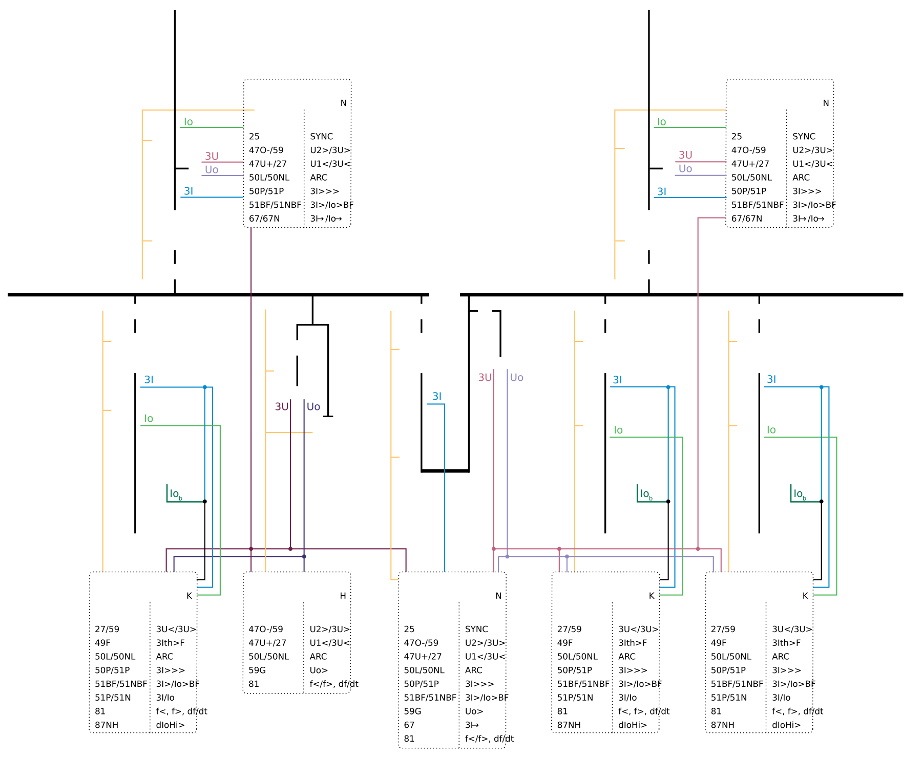
Core incomer functions
- 50/51 phase overcurrent: backup for feeder, bus and source-connection faults. The time-delayed stage must coordinate with the slowest downstream protection while remaining within the source transformer/cable and switchgear withstand limits.
- 50N/51N or 50G/51G earth fault: selected according to network earthing. The incomer earth-fault stage may provide bus backup, but it should not trip before a healthy outgoing feeder has had time to clear its own fault.
- 67/67N directional overcurrent: needed when fault current can flow both into and out of the bus—for example parallel transformers, closed bus ties, generators, large motor contribution or a ring network. Directional polarization must remain valid during depressed voltage and VT fuse failure.
- 50BF breaker failure: retrips the incomer, then trips the next upstream breaker or all other sources to the bus if current persists or the breaker auxiliary contacts do not indicate successful opening.
- 74TCS and breaker supervision: supervise trip coil, DC supply, breaker position discrepancy, spring charge, gas pressure where applicable and operation count.
- Fault and disturbance recording: record phase/zero-sequence currents, voltages, binary trips, breaker position and interlocking signals with a synchronized clock.
Functions that depend on the scheme
- 27/59 and 81U/81O: source-quality protection, transfer initiation, load shedding or island detection. Do not trip an incomer for a transient voltage dip unless the process philosophy requires it.
- 81R (ROCOF) and vector-shift methods: possible islanding aids, but they require system-specific stability and nuisance-trip studies.
- 32 reverse power: prevents unintended export or protects a prime mover where the incomer is generator-fed. Set direction from the CT/VT polarity and the contractual power-flow definition.
- 25 synchronism check: required before closing between live systems or bus sections. Dead-bus/dead-line logic, voltage difference, slip frequency, angle and breaker closing time must be engineered together.
- 87B bus differential: preferred main protection for important buses when fast, selective clearing is required. It is not an “incomer function,” but incomers and couplers are trip outputs of the bus zone.
- 50ARC arc protection: light plus overcurrent can provide very fast internal-arc clearing. Zone-select light sensors, supervise the current criterion and trip every source feeding the affected zone.
- 50SOTF switch-onto-fault: accelerates clearing when the breaker is closed onto a pre-existing fault.
Incomer selectivity strategies
Three common approaches are used, sometimes together:
- Time grading: downstream feeders operate first, followed by the incomer and then the upstream source. It is simple but can produce an unacceptably long bus-fault clearing time.
- Zone-selective interlocking or blocking: a downstream start signal blocks or restrains the incomer high-speed stage. If the incomer sees fault current but receives no downstream block, it treats the fault as a bus fault and trips quickly. Signal failure philosophy, communications latency and a backup timer are essential.
- Bus differential or arc protection: gives a dedicated, fast bus zone and leaves overcurrent as backup. This is usually the most selective approach for high short-circuit levels or stringent arc-energy targets.
A 1,250 A breaker does not imply a 1,250 A load pickup. The continuous-load limit may be set by the transformer, cable, bus, ventilation or contract demand. The minimum fault seen through the weakest source condition—not the maximum fault—sets the sensitivity test.
Incomer setting checks
| Element | Lower constraint | Upper constraint | Coordination check |
|---|---|---|---|
| 51 phase pickup | Maximum legitimate load, emergency loading, cold-load pickup and measurement tolerance | Minimum downstream phase-fault current divided by the required sensitivity margin; protected conductor/transformer thermal limit | Above downstream load elements; slower than the slowest downstream clearing time plus breaker, relay and safety margins |
| 50/51 high stage | Transformer inrush, motor contribution, downstream close-in fault that should remain selective, CT transient error | Minimum bus or source-connection fault that must be cleared rapidly | Check instantaneous reach through transformers and parallel-source states; apply blocking or direction if needed |
| 51N/67N | Standing residual, CT mismatch, system capacitive current and neutral-resistor tolerance | Minimum earth-fault current at the remote end | Coordinate with feeder earth-fault elements for every earthing and bus-tie state |
| 50BF | Breaker opening time plus relay dropout/current decay | Maximum acceptable backup clearing time | Verify retrip, current check, contact check, upstream trip and bus-source isolation |
6. General outgoing line and cable feeders
A general outgoing feeder supplies another switchboard, a distribution line, a cable circuit or a mixed overhead/cable route. Its protection must clear faults within the feeder zone while coordinating with downstream devices and preserving healthy circuits.
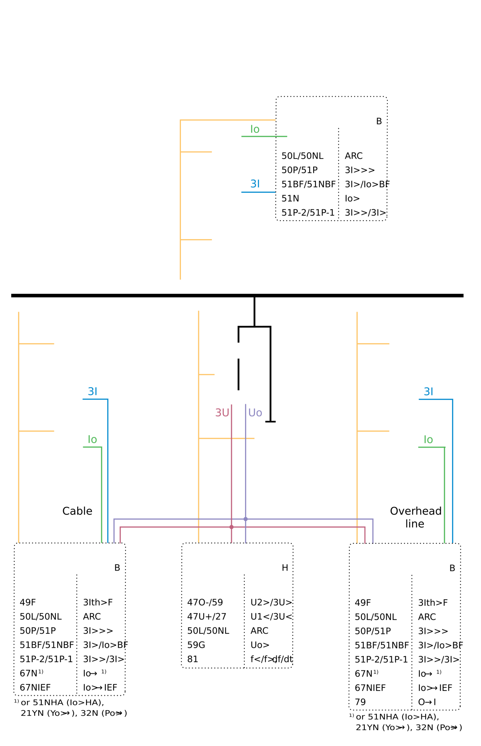
Minimum practical scheme
- 50/51 phase overcurrent for phase faults and high-current overload backup.
- Earth-fault protection matched to the earthing method: 50N/51N, 67N, sensitive CBCT, wattmetric/admittance or transient methods.
- 50BF where failure of the feeder breaker must trip the incomer or bus zone.
- 74TCS, breaker-condition supervision and event recording.
When additional functions are justified
- 67/67N: closed-ring operation, distributed generation, parallel paths or significant reverse motor contribution.
- 46 negative-sequence current: broken conductor, severe current unbalance or backup for phase-to-phase faults at low magnitude. It is more sensitive to unbalance than a simple phase overcurrent element.
- 49 cable thermal model: heavily loaded cables, varying ambient/soil conditions or cyclic loading. The model must represent the actual conductor, installation and cooling; it is not a substitute for a proper cable rating study.
- 27/59, 59N and 81: voltage/frequency supervision, islanding, load shedding or feeder-specific process requirements.
- 21 distance or 87L line differential: critical, long, high-value or weak-infeed circuits where overcurrent cannot give sufficient speed, sensitivity or selectivity. Line differential requires a dependable communications channel and end-to-end testing.
- 50ARC: for cable compartments, breaker compartments and switchgear bus zones where arc-energy reduction is required.
- 79 autoreclose: normally limited to overhead-line circuits with a high probability of transient faults. Define shot count, dead time, reclaim time, synchronism/dead-line checks and lockout conditions.
Do not automatically reclose a feeder supplying a transformer, motor, capacitor bank or predominantly cable circuit. A permanent cable fault, trapped motor flux, transformer fault or charged capacitor bank can make an automatic reclose damaging. If any reclose is proposed, perform a specific equipment, process and safety review.
Overcurrent coordination principles
For a time-overcurrent pickup, the feasible region can be expressed conceptually as:
The chosen curve and time dial must then:
- remain above load, cold-load pickup, transformer inrush or motor-start current that the feeder is expected to carry;
- operate before the cable short-circuit withstand or connected-equipment damage curve is exceeded;
- allow the downstream fuse/relay and breaker to clear first, including relay overtravel, breaker time, CT error and an explicit grading margin;
- remain selective for both maximum and minimum fault levels and all credible topology states; and
- respect the breaker’s short-time withstand and interrupting rating.
IEC 60255-151 defines functional requirements for overcurrent and undercurrent protection, but it does not provide universal pickup settings. Curve family names alone are insufficient: verify the exact relay equation, reset characteristic, timer behavior and tolerance.
7. Transformer outgoing-feeder protection
A transformer feeder contains two overlapping protection problems: the MV cable/breaker zone and the transformer unit itself. Time-overcurrent can back up both, but it is not equivalent to transformer differential protection.
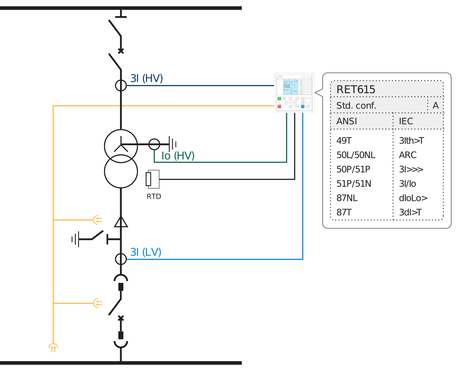
Main electrical protection
- 87T transformer differential: fast main protection for internal phase and earth faults within the CT boundary. It must compensate ratio, vector group and zero-sequence differences, tolerate tap-changer range and remain stable for external faults with CT saturation.
- 64REF/87N restricted earth fault: highly sensitive protection for earth faults in a grounded star winding between the phase CTs and neutral CT. REF often detects low-current faults close to the neutral that percentage differential or overcurrent may miss.
- 50/51 phase and 50N/51N earth overcurrent: backup for internal faults and primary protection for external lead/cable faults outside the differential zone. Coordinate with LV-side devices and transformer through-fault withstand.
- 46 negative sequence: protection against sustained unbalanced loading and backup for unbalanced faults where appropriate.
- 49 thermal overload: based on transformer loading and thermal data. For oil-immersed transformers, hot-spot and top-oil behavior may be integrated with direct temperature inputs or a dedicated monitor.
- 24 volts-per-hertz overexcitation: required where excessive V/Hz can occur, particularly generator step-up/service arrangements or systems exposed to frequency depression and voltage-control errors.
Mechanical and temperature protection
Oil-immersed transformer protection commonly includes Buchholz gas/surge (63) where a conservator is fitted, sudden-pressure or pressure-relief devices, oil-level alarm, top-oil temperature and winding-temperature indication. Dry-type units use winding RTDs/thermistors and enclosure/ambient sensors. These devices are not optional “relay extras”: their contacts must be assigned to alarms, trips, cooling control and lockout according to the transformer manufacturer’s instructions.
Inrush, overexcitation and CT performance
Energization can produce high, asymmetric magnetizing current. Transformer differential relays use harmonic or waveform-based restraint/blocking to remain stable for inrush while still detecting an internal fault during energization. Overexcitation may also generate harmonic content but is a different physical condition and should be handled by the V/Hz function and the relay’s specific differential logic. Do not assume that “second-harmonic blocking” alone solves all energization cases.
For external faults, unequal CT saturation can create false differential current. Select CTs and settings using maximum through-fault current, X/R ratio, secondary burden, lead resistance, transformer ratio/tap range and the relay manufacturer’s CT performance method. IEEE C37.110 provides guidance on CT application; transformer through-fault withstand and protection coordination should also be checked against IEC 60076-5 and IEEE C57.109.
Trip philosophy
| Condition | Typical action | Reason |
|---|---|---|
| 87T, REF, Buchholz trip, sudden pressure | Trip every source to the transformer, operate 86 lockout, block automatic reclose/transfer | Internal fault may remain energized from either side; re-energization requires investigation |
| MV feeder phase/earth fault outside unit zone | Trip MV feeder breaker; upstream breaker through 50BF if required | Isolate the feeder lead without unnecessary LV trip if the defined zone permits |
| Thermal alarm / first temperature stage | Alarm, start cooling, reduce load | Allows corrective action before insulation life is endangered |
| Thermal trip / severe V/Hz | Trip designated sources; lockout depends on cause and operating policy | Prevent cumulative thermal or core damage |
| LV breaker failure or downstream fault backup | Intertrip MV breaker after coordinated delay | MV source must clear when the LV breaker cannot |
A time-overcurrent feeder relay and MV fuse may be acceptable for some small transformers, subject to local practice and a coordination study. However, overcurrent alone can be insensitive to low-level internal winding faults. Transformer size, criticality, fire consequence, continuity requirement, grounding and the availability of CTs on both sides should drive the decision to apply 87T and REF.
8. MV motor-feeder protection
A motor feeder must distinguish a normal but severe starting event from a stalled, jammed or faulted machine. Phase overcurrent alone cannot do this reliably. The central protection is a motor thermal model supported by start supervision, negative-sequence protection and process-aware logic.
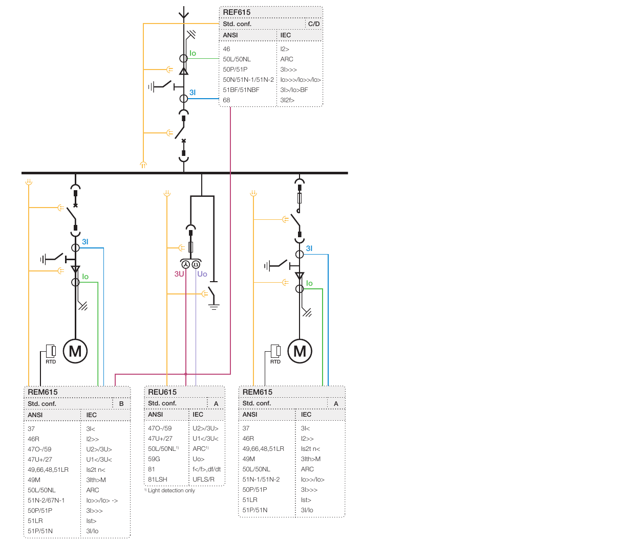
Essential motor functions
- 49 motor thermal overload: estimates stator/rotor heating from current, negative sequence, start history and cooling state. Use manufacturer cold/hot withstand curves and, where available, RTD bias or direct temperature supervision.
- 48 / 51LR start-time, stall and locked-rotor protection: supervises starting current against actual acceleration time and detects a running motor that stalls. Separate starting and running logic avoids compromising either condition.
- 46 negative-sequence current: protects the rotor from heating caused by voltage/current unbalance, phase loss and some turn/connection abnormalities. Motor negative-sequence withstand is usually much lower than positive-sequence thermal capacity.
- 50 instantaneous and 51 phase overcurrent: short-circuit protection and backup. The high-set stage must be secure for maximum starting current, asymmetry and CT transient response yet sensitive to the minimum fault in its intended zone.
- 50N/51N or sensitive earth fault: detects stator/feeder earth faults according to the network earthing. A CBCT is often used where high sensitivity is needed.
- 66 starts-per-hour / restart inhibit: prevents another start until the motor has sufficient thermal capacity. It should account for consecutive cold starts, hot starts, minimum stop time and, where relevant, load backspin.
- RTD/temperature inputs: stator winding and bearing temperatures provide direct evidence that a current-only thermal model cannot fully capture, such as blocked ventilation or bearing failure.
Conditional motor functions
- 37 undercurrent or underpower: loss of load, dry-pump, broken belt, uncoupled load or pump cavitation. Apply start and process delays to avoid trips during legitimate low-load operation.
- 47 phase-sequence / voltage unbalance: blocks or trips for wrong phase rotation, phase loss or excessive supply-voltage unbalance.
- 27/59 and 81: undervoltage release, ride-through, reacceleration sequencing, overvoltage and frequency protection. Coordinate with plant load-shedding and automatic restart philosophy.
- 87M motor differential: fast, sensitive internal-fault protection for large or critical motors when six winding leads or suitable terminal/neutral CTs are available.
- 50ARC and 50BF: switchgear arc protection and breaker-failure escalation for breaker-fed motors.
- Speed, vibration, bearing, seal and process inputs: often supplied by the machine monitoring or control system but may initiate relay alarm/trip logic.
Circuit breaker versus contactor and fuse
A breaker-fed motor relay can trip the breaker for all assigned faults within the breaker duty. In a contactor-and-fuse starter, the current-limiting fuse clears high-current short circuits while the contactor interrupts overload, stall and normal switching currents. The protection logic must not command the contactor to interrupt beyond its rated breaking capacity. Coordinate:
- fuse minimum-melting and total-clearing curves with motor starting and contactor withstand;
- relay trip transfer to the contactor below the fuse/contactor crossover current;
- fuse failure or phase-loss detection to prevent single phasing; and
- contactor dropout, latch and restart behavior after auxiliary-voltage loss.
Data required for settings
| Data | Used for | Why nameplate current alone is insufficient |
|---|---|---|
| Rated kW, voltage, full-load current, power factor, efficiency and service factor | Base current, overload model and load thresholds | Mechanical power does not equal electrical input; process loading may be below or above nominal |
| Locked-rotor current and safe-stall time, cold and hot | 48/51LR and 49 | Two motors of equal kW can have different start current and thermal withstand |
| Actual acceleration time versus load and voltage | Start supervision and undervoltage ride-through | Protection must clear a failed start but not a normal worst-case start |
| Permitted starts cold/hot, minimum stop time and load backspin time | 66 restart inhibit | Rotor and driven process may not be ready even when the stator appears cool |
| Negative-sequence withstand I22t or manufacturer curve | 46 pickup and time characteristic | Rotor heating from unbalance is disproportionate to average phase current |
| RTD type, locations, alarm/trip temperatures | Direct thermal protection | Bearing and winding hot spots may not track current model temperature |
| Earthing method and minimum stator/feeder earth fault | 51N/67N/CBCT design | Earth-fault current may be resistor- or capacitance-limited |
| Contactor, breaker and fuse curves/ratings | Fault interruption and coordination | The switching device must clear the commanded current safely |
Motor setting philosophy
Plot the motor starting envelope and the cold/hot thermal-damage curves on the same current-time axes as the relay. The start element should allow the longest legitimate acceleration at the lowest permissible voltage, while the stall element should trip within the safe-stall time. The thermal model should preserve memory through stop/restart and power interruption according to actual cooling. Verify CT performance at asymmetrical start and short-circuit current.
Automatic restart requires an explicit process decision. Check residual motor voltage and phase angle, motor and load reacceleration torque, total bus voltage dip, starts-per-hour, essential/nonessential load priority and whether a common voltage event could restart many motors simultaneously.
9. MV capacitor-bank feeder protection
Capacitor protection is topology-dependent. The most important internal-failure protection is usually an unbalance measurement selected for the bank connection. General feeder overcurrent is backup; it may not detect the loss of a single capacitor element or unit before the surviving elements are overstressed.
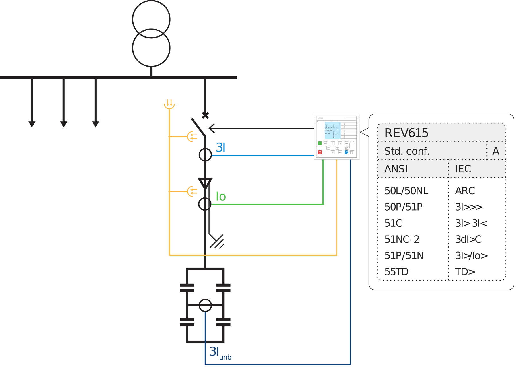
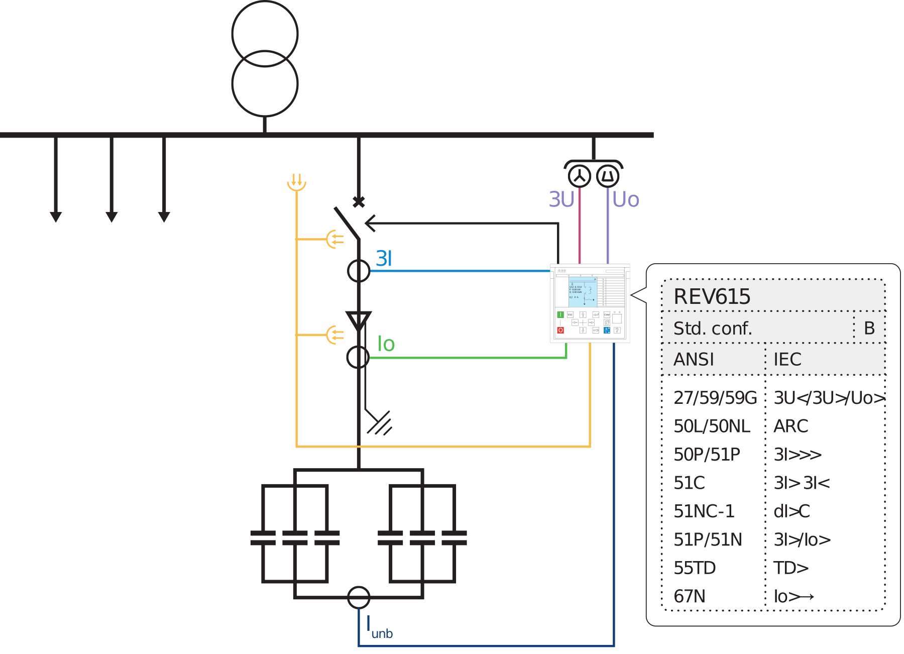
Protection by bank connection
| Bank arrangement | Primary internal-failure quantity | Typical implementation | Design notes |
|---|---|---|---|
| H-bridge | Difference between bridge-leg currents in each phase | Three-phase current-unbalance protection, with natural-unbalance compensation | High sensitivity to unit/element failures; CT ratio, polarity and bridge symmetry are critical |
| Ungrounded double star (double wye) | Current between the two star points | Neutral-current unbalance, typically alarm and trip stages | Compensate inherent manufacturing/system unbalance; verify external-fault stability |
| Ungrounded single star | Neutral displacement voltage | 59N/neutral-voltage unbalance from a VT or sensing device | Coordinate with system ground-fault voltage and VT ferroresonance considerations |
| Grounded single star | Neutral current and/or phase imbalance | Sensitive neutral-current unbalance; sometimes voltage or unit-level sensing | Separate element-failure unbalance from system earth-fault current and harmonics |
| Harmonic filter bank | Unbalance plus reactor/resistor thermal stress and harmonic current | Bank unbalance, RMS/harmonic overload, reactor/resistor temperature, overcurrent and overvoltage | Protection must represent tuning frequency and expected harmonic spectrum, not only fundamental current |
Essential capacitor-bank functions
- Unbalance alarm and trip: detect failed elements/units before voltage across the remaining series elements exceeds the manufacturer’s permissible value. Use natural-unbalance compensation and establish the healthy baseline during commissioning.
- 50/51 phase overcurrent: clears feeder leads, bus connections and high-current internal faults; coordinate with capacitor-unit fuses and switching transients.
- Earth-fault protection: detects feeder or bank-to-ground faults according to bank grounding and system earthing. Do not confuse system zero-sequence protection with the dedicated internal-unbalance element.
- Thermal/RMS overload: protects capacitors and series reactors from sustained current including harmonic content. Fundamental-frequency current alone can underestimate heating.
- 59 overvoltage or capacitor-specific inverse-time overvoltage: protects against sustained system voltage that raises dielectric stress and reactive current. Coordinate with IEC 60871-1 limits and manufacturer data.
- 27 undervoltage / de-energization logic: releases the bank when system voltage is lost or too low, subject to process requirements, and supports safe transfer logic.
- 50BF, trip-circuit supervision and lockout/reclose inhibit: failure to isolate a faulted bank can rapidly escalate damage.
Switching, inrush and discharge
Capacitor energization creates high-frequency inrush. Back-to-back switching—energizing a bank onto a bus with another bank already charged—can produce especially high peak current. Evaluate breaker switching duty, pre-insertion devices or controlled switching where applicable, series reactors, CT transient response and relay high-set security. Never raise instantaneous pickup blindly to “get past inrush”; verify that the remaining element still detects the intended fault.
After opening, the bank retains charge until its discharge devices reduce the voltage. Reclosing must be blocked for the manufacturer-specified discharge interval or until a reliable residual-voltage measurement proves it safe. The interval is not a universal fixed number. Include breaker auxiliary contact validation, undervoltage/undercurrent confirmation and a timer whose reset behavior is tested after DC supply interruption.
Unbalance settings are calculated, not guessed
Translate the loss of one element or unit into the relay quantity using the actual series/parallel arrangement, element capacitance tolerance, fuse philosophy, CT/VT ratio and system-voltage unbalance. Then establish at least two levels where justified:
- Alarm: early element/unit loss that should be inspected before the next failure;
- Trip: the failure level at which remaining elements approach their permissible voltage/current stress.
Check sensitivity for the smallest failure, security for healthy natural unbalance, external phase faults, energization and harmonics, and stability over the full system-voltage range. IEC TS 60871-3 specifically addresses protection of shunt capacitor banks, while IEC 60871-1 provides bank/unit performance and testing requirements.
10. CT, CBCT and VT engineering
Instrument transformers define what the relay can see. Protection settings should never be finalized before the measurement chain is checked.
Current transformers
- Ratio: provide usable resolution at minimum fault and normal load while keeping maximum through-fault and transient performance within the CT/relay capability. A ratio selected only from breaker rating may sacrifice sensitivity.
- Accuracy and saturation: assess fault current, X/R ratio, remanence assumption, secondary burden, lead resistance and relay input burden. Differential, REF and high-impedance schemes have specific CT matching or knee-point requirements.
- Location and polarity: the physical CT location defines the zone. Confirm P1/P2 and S1/S2 polarity against the relay direction convention and single-line drawing. A reversed CT can make 67, 87 or power elements insecure.
- Secondary grounding: use one intentional grounding point per galvanically connected CT circuit unless the approved design specifies otherwise. Multiple grounds can create circulating current; no ground creates a dangerous floating circuit.
- Open-circuit safety: never open an energized CT secondary. Provide test blocks and shorting facilities designed for safe injection and maintenance.
Core-balance CTs
A CBCT measures the vector sum of all phase-conductor currents directly and is therefore well suited to sensitive earth-fault protection. Route all phase conductors through the core in the same direction. For shielded cables, route the cable screen/grounding conductor according to the required cancellation arrangement; a screen lead passing incorrectly through the core can cancel the fault current or create false residual current. Keep secondary leads twisted/shielded as required and verify polarity by primary injection.
Voltage transformers and fuse-failure supervision
Voltage-dependent functions need a clear measurement reference: bus VT, line VT, open-delta residual voltage or neutral VT. Check VT ratio, connection, phase rotation, burden, fuse/MCB monitoring, ferroresonance mitigation and grounding. Fuse-failure or VT-circuit supervision should block voltage-polarized elements that could misoperate while leaving current-only backup active. For synchronism check, confirm that the two voltages represent the actual systems on either side of the closing breaker.
11. From study results to relay settings
A defensible settings calculation traces every value to an input, inequality and coordination check. Typical input cases include:
- maximum and minimum utility source, transformer taps and generator dispatch;
- bus coupler open/closed and parallel transformer operation;
- maximum load, emergency load, cold-load pickup and motor starting;
- minimum remote-end phase and earth faults;
- maximum close-in through fault and CT saturation case;
- equipment damage/withstand and downstream clearing curves; and
- communications or interlocking failure fallback.
Useful base-current equations
These calculate base current only. They do not set relay pickup. Apply equipment tolerances, voltage variation, overload capability, harmonic current, measurement error and the protection objective.
Coordination margins
A grading margin is the sum of specific uncertainties, not a traditional number copied from another project. Account for downstream breaker clearing time, upstream breaker time, relay timing tolerance, CT error/saturation, overshoot or reset behavior, communications latency and a documented engineering margin. Digital relays and modern breakers may permit tighter grading than old electromechanical schemes, but only when the complete operating-time chain is known and tested.
High-set elements
For each instantaneous or definite-time high stage, plot:
- maximum transformer inrush and sympathetic inrush;
- motor locked-rotor and starting asymmetry;
- capacitor inrush and back-to-back switching peak;
- maximum downstream through fault that should remain selective;
- minimum in-zone fault that must operate; and
- CT saturation and relay transient/peak response.
If there is no secure gap, use direction, differential protection, zone interlocking, communications-assisted logic or a short intentional delay. Do not create a blind zone merely to avoid nuisance trips.
Setting groups
Multiple setting groups are useful when the network genuinely has distinct operating states, such as bus-tie open versus closed or utility-parallel versus islanded operation. Group selection must be deterministic, supervised and recorded. Define the safe default if a selector input or communications signal fails, and test the transition with current flowing.
12. Trip matrix, breaker failure and lockout
A relay element is only useful if its output isolates every source feeding the faulted zone. The cause-and-effect matrix should be approved alongside the settings.
| Initiating condition | First action | Escalation / block | Reset philosophy |
|---|---|---|---|
| Outgoing feeder 50/51 or earth fault | Trip local feeder breaker | 50BF retrip, then trip incomer/bus sources; block feeder reclose if fault is permanent or equipment-fed | Relay automatic reset may be acceptable; breaker/SCADA alarm acknowledged |
| Bus differential or confirmed arc | Trip all incomers, couplers and sources in the affected zone | Block transfer and automatic reclose; upstream intertrip if a source breaker fails | Manual inspection and lockout reset normally required |
| Transformer 87T/REF/mechanical trip | Trip breakers on all transformer sides | Operate 86, block re-energization and automatic transfer onto the unit | Manual reset after investigation |
| Motor thermal/stall/negative sequence | Trip breaker or contactor within its interrupting duty | Set restart inhibit based on thermal capacity and process state | Automatic only when thermal/process criteria are satisfied; otherwise manual |
| Capacitor unbalance alarm | Alarm and record phase/quantity | Maintenance action before additional unit failure | After inspection or confirmed healthy baseline |
| Capacitor unbalance trip / severe overload | Trip bank breaker | Block reclose until discharge and inspection criteria are satisfied | Normally manual for internal-failure trip |
| Breaker failure | Retrip same breaker via alternate trip coil where available | Trip the smallest set of upstream/adjacent breakers that removes all fault current | Manual investigation; event and current evidence retained |
Breaker-failure design details
Start 50BF only from a legitimate trip that requires current interruption. Use phase and residual current checks suited to the fault type and, where needed, breaker auxiliary-contact supervision. Set the timer above the worst-case breaker opening plus arc-extinction, relay dropout and margin, but below the maximum acceptable backup clearing time. Confirm the escalation trips every alternate source—including bus couplers, generators and transformer backfeed. Testing must include a simulated stuck breaker, not merely operation of the start bit.
Lockout relay 86
Use lockout for conditions where automatic re-energization could worsen damage or endanger personnel: transformer internal/mechanical trips, confirmed bus arcs and severe capacitor-bank internal faults are common examples. Define whether 86 is physical, numerical or both; how it is powered; which breakers it trips/blocks; and who may reset it. A lockout that can be remotely reset without inspection defeats its purpose.
13. Arc protection and arc-energy reduction
Conventional time grading may allow a bus or switchgear arc to persist for hundreds of milliseconds. Arc protection uses optical sensors, often supervised by an overcurrent criterion, to trip rapidly. Good design requires:
- sensor coverage by compartment and a documented arc zone;
- a current criterion that is sensitive at the minimum arcing current but secure during normal switching;
- tripping of every source and coupler feeding the zone;
- fast, direct output contacts or a verified communications path;
- sensor and fiber/cable supervision where provided;
- breaker total clearing time included in the incident-energy calculation; and
- commissioning with controlled light/current simulation and end-to-end trip timing.
Maintenance-mode instantaneous elements, zone-selective interlocking, differential protection and remote racking/switching can also reduce exposure. Any maintenance switch that lowers pickup or delay must be access-controlled, visibly indicated, alarmed and returned to normal after work.
14. IEC 61850, communications and records
IEC 61850 GOOSE can carry blocking, intertrip, breaker-failure and bus-transfer signals with high speed. The protection design must still define the behavior for network, switch, time-sync or merging-unit failure. For critical signals, evaluate redundant networks, message supervision, quality bits, fail-safe fallback and whether a hardwired independent path is justified.
Engineering records should include the relay model and order code, firmware, settings file and checksum, logic diagrams, IEC 61850 configuration revision, signal list, CT/VT data, calculation report, approved coordination curves, test plans, as-left results, disturbance-record channel map and time-sync architecture. Cybersecurity controls should preserve protection availability: authenticated role-based access, controlled settings changes, backups, security logging and a documented recovery path.
15. Illustrative 20 kV switchboard example
Consider a 20 kV industrial board with a 1,250 A incomer breaker, a 400 A general cable feeder, a 2.5 MVA transformer feeder, a 1 MW motor and a 3 MVAr capacitor bank. The figures below establish only primary base currents:
| Feeder | Illustrative data | Calculated base current | What is still missing before settings |
|---|---|---|---|
| Incomer | 1,250 A breaker | Not derivable from breaker rating | Source transformer/line rating, actual maximum load, bus rating, max/min faults, parallel states and downstream grading |
| General cable | 400 A feeder rating | Not necessarily 400 A load | Cable type/length/installation, ampacity, short-circuit withstand, remote minimum fault, downstream devices and earth-fault current |
| Transformer | 2.5 MVA, 20 kV | 2,500 kVA ÷ (√3 × 20 kV) = 72.2 A | Vector group, impedance, tap range, inrush, CTs, LV rating/grounding, damage curve, through faults and differential zone |
| Motor | 1,000 kW, assumed η = 0.95 and pf = 0.90 | 1,000 kW ÷ (√3 × 20 kV × .95 × .90) = 33.8 A | Nameplate current, locked-rotor current, start time, cold/hot stall curve, starts/hour, RTDs, load torque and supply dip |
| Capacitor bank | 3 MVAr, 20 kV | 3,000 kVAr ÷ (√3 × 20 kV) = 86.6 A | Connection, series/parallel units, element fuses, capacitance tolerance, unbalance calculation, harmonics, reactor, inrush and discharge time |
Preliminary function schedule
| Panel | Minimum preliminary functions | Enhanced / conditional functions |
|---|---|---|
| Incomer | 50/51, earth fault appropriate to earthing, 50BF, 74TCS, disturbance recorder | 67/67N for parallel/backfeed, 27/59/81, 32, 25, 50ARC, bus differential trip interface, zone interlocking |
| Cable feeder | 50/51, appropriate earth fault, 50BF/74TCS | 67/67N, 46, 49 cable, 21 or 87L, 50ARC; 79 only if the circuit is suitable overhead line |
| Transformer feeder | 50/51 and earth-fault backup, temperature/mechanical inputs, 50BF/74TCS | 87T and REF based on size/criticality, 49, 24, 46, arc protection and 86 lockout |
| Motor feeder | 49, 48/51LR, 46, 50/51, earth fault, 66, RTDs where available | 37, 47, 27/59/81, 87M for large/critical motor, arc and breaker-failure protection |
| Capacitor feeder | Topology-specific unbalance, 50/51, earth fault, RMS/harmonic overload, 59, discharge/reclose interlock | Reactor/resistor thermal inputs, resonance supervision, arc and breaker-failure protection, staged alarm/trip compensation |
Suppose the motor’s actual locked-rotor current were six times the estimated full-load current; the starting current would be about 203 A primary. That number is still not a pickup setting: the actual manufacturer current, tolerance, DC offset, CT response and start duration must be compared with the start/stall curve. The example demonstrates why apparent “easy” settings require equipment data.
16. Relay application examples by manufacturer
Modern numerical relays are modular; the exact available functions depend on ordered hardware, application package, firmware and licensing. The following examples are application families, not a procurement specification.
| Application | Siemens SIPROTEC 5 examples | ABB Relion 615 examples | Other official examples |
|---|---|---|---|
| Incomer / general feeder | 7SJ82 and 7SJ85 overcurrent protection families | REF615 | Schneider Electric PowerLogic P3 application variants; SEL-751 |
| Transformer feeder / unit | 7UT82/7UT85 differential protection families; 7SJ82/85 may provide feeder backup | RET615 | Use a dedicated transformer differential relay when 87T/REF are required; verify CT inputs and vector-group compensation |
| Motor feeder | 7SK82/7SK85 motor-protection families | REM615 | Confirm thermal model, RTD inputs, start/stall logic and breaker-versus-contactor application |
| Capacitor bank | 7SJ82/7SJ85 application capability includes capacitor-bank protection; verify the required unbalance inputs | REV615 | SEL capacitor-bank protection comparison shows functions such as breaker failure, overvoltage, unbalance and voltage differential across product options |
Siemens’ official SIPROTEC 5 brochure maps the 7SJ82/7SJ85 families to overcurrent applications, 7SK82/7SK85 to motor protection and 7UT82/7UT85 to transformer differential applications. A brand name never substitutes for an input/output and function checklist. Verify current and voltage inputs, CBCT/neutral inputs, RTDs, binary I/O, arc sensors, communications redundancy, time synchronization, logic capacity, disturbance records and local service support.
17. Commissioning and periodic testing
Protection commissioning must prove the complete scheme, not just that a relay element changes state on a laptop.
- Document control: confirm approved drawings, calculations, firmware, settings revision, logic and IEC 61850 configuration.
- Wiring and insulation checks: verify CT/VT continuity, polarity, grounding, test-block positions, trip circuits and DC supply. Never megger through connected electronics or closed CT secondary paths contrary to manufacturer instructions.
- Primary checks: where practical, inject primary current to prove CT ratio, polarity, phase association and CBCT installation. Confirm VT ratio and phase sequence from the primary system.
- Secondary injection: test pickup, dropout, operating time, direction, characteristic points, thermal/start logic, harmonic restraint and all setting groups.
- Logic tests: prove every block, permissive, interlock, alarm, local/remote condition, fuse-failure response, 86 latch and reset path.
- Trip-path tests: trip the actual breaker or use an approved trip test with isolation controls; record relay output, trip-coil current, breaker travel/open time and final current interruption.
- Breaker failure: simulate failure to open and prove retrip plus the correct upstream/adjacent trips.
- Communications-assisted schemes: perform end-to-end tests for line differential, GOOSE blocking/intertrip and time synchronization, including loss-of-channel behavior.
- Equipment-specific tests: transformer vector-group/differential stability; motor start record and thermal behavior; capacitor healthy unbalance baseline, trip stages and discharge interlock.
- Closeout: retrieve COMTRADE/events, confirm sequence-of-events timestamps, seal test switches, save as-left files and issue a signed test report.
Periodic intervals should be risk-based and consider relay self-supervision, breaker mechanism condition, DC system health, environmental exposure, operations count, prior failures and regulatory requirements. Numerical relays reduce calibration drift but do not test the breaker, trip coil, CT wiring, optical arc sensor or human change-control process.
18. Project data checklist
| Applies to | Minimum project data before final protection design |
|---|---|
| All feeders | Approved single-line and schematics; voltage and frequency; earthing; normal/alternate topology; max/min short-circuit results; load flow; CT/VT data; breaker ratings/times; DC system; trip matrix; downstream devices; arc-flash requirements; communications and time sync |
| Incomer | Source transformer/generator/utility limits; parallel operation; permitted import/export; transfer sequence; bus differential/arc zones; load shedding; upstream intertrip and breaker-failure destination |
| Line/cable | Conductor type, size, length and installation; ampacity and short-circuit withstand; overhead/cable proportion; remote source/DG; line charging; downstream protection; communications channel if 87L |
| Transformer | MVA, ratios, vector group, impedance, tap range, grounding; inrush and thermal/through-fault data; CTs both sides; cooling; 63/26/71 contacts; LV protection; differential/REF zone |
| Motor | Nameplate and manufacturer protection data; start current/time and safe-stall curves; starts/hour; load torque/inertia; RTDs; supply dip/restart philosophy; breaker/contactor/fuse duties; process trip inputs |
| Capacitor bank | MVAr, connection, grounded/ungrounded neutral; unit and element series/parallel arrangement; internal/external fuses; capacitance tolerance; CT/VT arrangement; reactor/filter tuning; harmonics; switching study; discharge device/time; permissible unbalance |
19. Common protection mistakes
- Copying another feeder’s settings. Similar load current does not mean similar minimum fault, inrush, earthing or equipment damage curve.
- Using breaker rating as protection pickup. The breaker frame is only one limit in a chain of cable, transformer, bus and load constraints.
- Applying nondirectional earth overcurrent on an isolated or compensated network. Magnitude may not identify the faulted feeder.
- Ignoring minimum-source conditions. A setting can operate perfectly for the maximum-fault case and be blind when one transformer or generator is out of service.
- Setting instantaneous overcurrent above every transient without checking sensitivity. This creates a blind high-speed zone; differential, direction or interlocking may be the correct solution.
- Treating transformer 51 as a substitute for 87T. Overcurrent is valuable backup but may be slow or insensitive for internal faults.
- Protecting a motor with generic feeder curves. Start, stall, negative-sequence heating and starts-per-hour require motor-specific logic.
- Protecting a capacitor bank only with 50/51. Element/unit failure may produce little feeder-current change; topology-specific unbalance is the primary detector.
- Enabling autoreclose on equipment feeders by habit. Cable, transformer, motor and capacitor circuits require explicit reclose justification.
- Ignoring CT saturation and polarity. The most sophisticated differential or directional function is insecure with unsuitable or reversed CTs.
- Testing the relay but not the trip path. A correct pickup does not prove DC supply, lockout, trip coil, breaker mechanism or upstream intertrip.
- Undocumented logic changes. A small programmable-logic edit can defeat selectivity even if numerical settings are unchanged.
20. Frequently asked questions
Does every MV feeder need voltage inputs?
No. A basic radial feeder in a solidly grounded system may be protected with current inputs. Voltage is required for functions such as 67/67N polarization, 27/59, 59N, 25, 32, 81 and some capacitor-bank schemes. Incomers often use bus voltage for supervision and transfer logic.
When is a CBCT preferable to the residual sum of three phase CTs?
When sensitive earth-fault pickup is needed, especially in resistance-grounded systems. A CBCT avoids phase-CT ratio and saturation mismatch in the residual sum. Its installation and cable-screen routing must be correct.
Can an MV cable feeder use autoreclose?
Usually it is blocked because cable faults are commonly permanent and reclosing can add damage. A mixed overhead/cable circuit may use reclose only after a specific study of the cable section, connected equipment, fault statistics and operating rules.
Is transformer differential always mandatory?
No universal size threshold applies everywhere. 87T becomes increasingly justified with transformer value, criticality, fire consequence, multiple sources, continuity needs and the requirement for fast sensitive internal-fault clearing. Local utility/company standards may mandate it above a stated rating.
Why is motor thermal overload different from feeder overload?
A motor model accounts for start heating, hot/cold state, locked-rotor withstand, negative-sequence heating, cooling while stopped and sometimes RTDs. A generic feeder 51 element does not represent these dynamics.
What is the key protection for a capacitor bank?
A connection-specific unbalance function—bridge current, neutral current, neutral voltage or voltage differential—normally provides the earliest detection of internal element/unit failures. Overcurrent, earth fault, overload, overvoltage and discharge interlocks complete the scheme.
Should GOOSE replace all hardwired trips?
Not automatically. GOOSE is well suited to fast interlocking and intertrip, but the architecture must meet dependability, security, latency, redundancy, supervision and cybersecurity requirements. Some critical trips may retain an independent hardwired path.
21. Conclusion
Successful MV feeder protection begins with failure modes and zones, not a relay catalog. The incomer needs selective source and bus backup; the outgoing feeder needs fault sensitivity and network-aware direction; the transformer needs unit protection and mechanical/thermal coverage; the motor needs a thermal/start model; and the capacitor bank needs connection-specific unbalance detection. Across all five, CT/VT performance, earthing, breaker failure, trip logic, arc-energy targets and commissioning determine whether the scheme works in the real switchboard.
A concise design rule is:
What failure does it detect? What is its exact zone? What legitimate condition must it ride through? Which breakers must it trip or block? What independent backup clears the fault if it or the breaker fails?
If those answers are supported by calculations and proven by end-to-end testing, the protection scheme is defensible. If they are not, adding more relay functions will not make it complete.
22. Standards and official manufacturer references
- IEC, IEC 60255-151:2009—Functional requirements for over/under current protection.
- IEC, IEC 60034-1:2026—Rotating electrical machines: Rating and performance.
- IEC, IEC 60871-1:2014—Shunt capacitors for AC power systems above 1,000 V.
- IEC, IEC TS 60871-3:2015—Protection of shunt capacitors and shunt capacitor banks.
- IEC, IEC 60076-7:2018—Loading guide for mineral-oil-immersed power transformers.
- IEC, IEC 60076-5:2006—Ability of power transformers to withstand short circuit.
- IEC, IEC 62271-200:2021 + AMD1:2024—AC metal-enclosed switchgear above 1 kV up to 52 kV.
- IEC, IEC 60909-0:2026—Short-circuit currents in three-phase AC systems.
- IEEE, IEEE C37.110-2023—Guide for the Application of Current Transformers Used for Protective Relaying Purposes.
- IEEE, IEEE C37.96-2012—Guide for AC Motor Protection.
- IEEE, IEEE C37.91-2021—Guide for Protecting Power Transformers.
- IEEE, IEEE C37.99-2012—Guide for Protection of Shunt Capacitor Banks. IEEE lists a current revision project; check status before contractual use.
- IEEE, IEEE C57.109-2018—Guide for Liquid-Immersed Transformer Through-Fault-Current Duration.
- ABB, REF615 Product Guide, 5.0 FP1 IEC.
- ABB, RET615 Product Guide, 5.0 FP1 IEC.
- ABB, REM615 Product Guide, 5.0 FP1 IEC.
- ABB, REV615 Product Guide, 5.0 FP1 IEC.
- Siemens, SIPROTEC 5—Digital Protection, Automation and Monitoring brochure.
- Schneider Electric, PowerLogic P3 Applications.
- Schweitzer Engineering Laboratories, SEL-751 Feeder Protection Relay and capacitor-bank protection comparison.